With more experience in the installation of tubular skylights, several problems have come to be identified.
In no particular order of priority, a first problem arises from recognition that different dimensions exist in different buildings between the exterior roof and the interior ceiling, and that those dimensions may vary greatly.
Economy in manufacture urges that
standardization of the light tunnels would be desirable, yet a single length of light tunnel, or even a limited series of standardized lengths, cannot account for the virtually infinite variations encountered in the field.
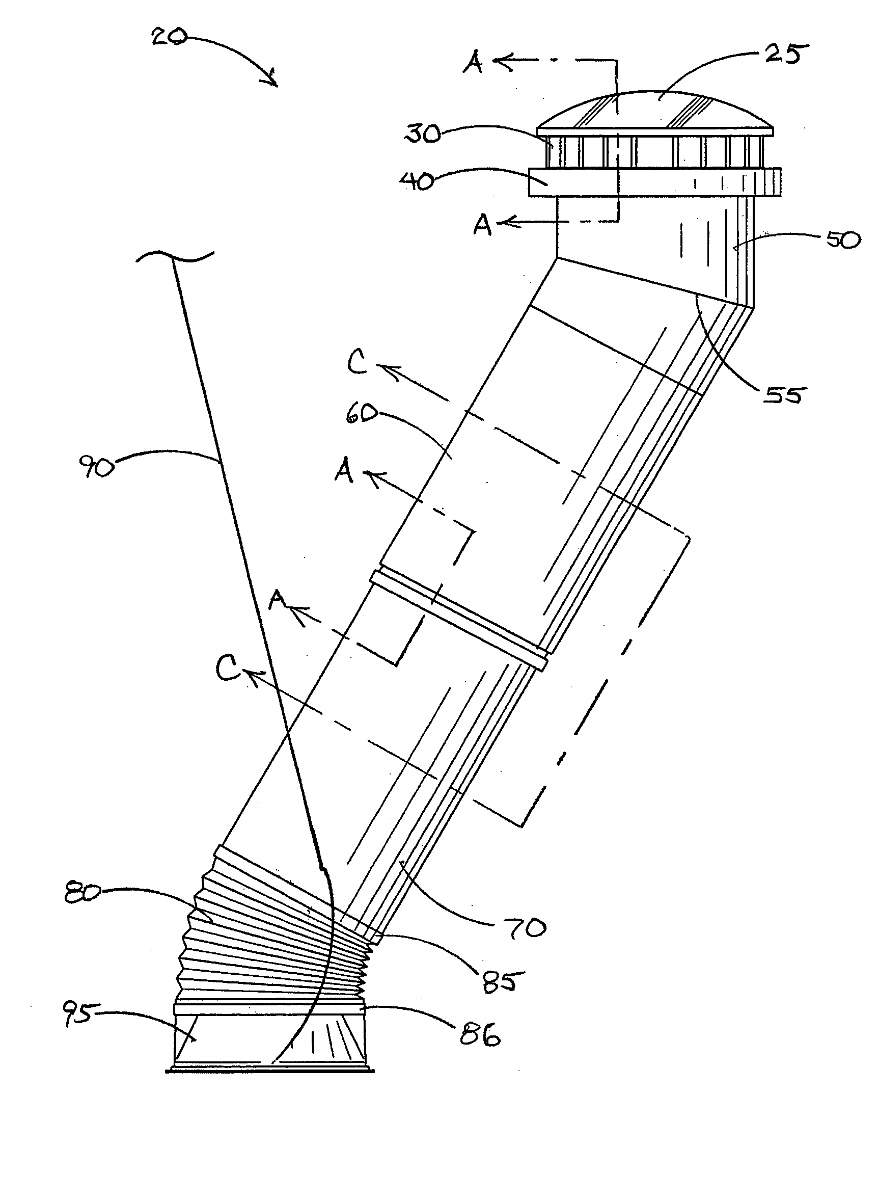
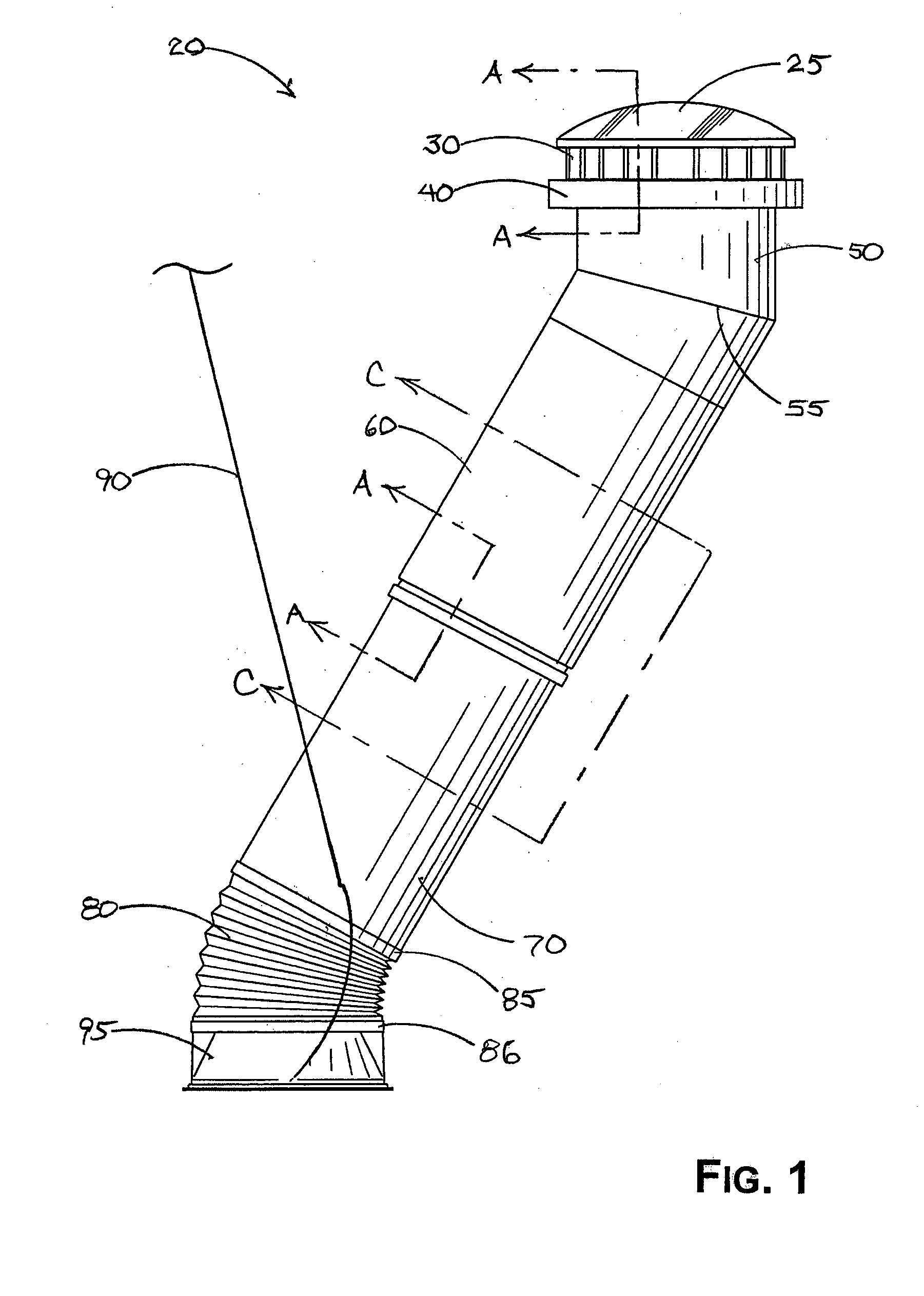
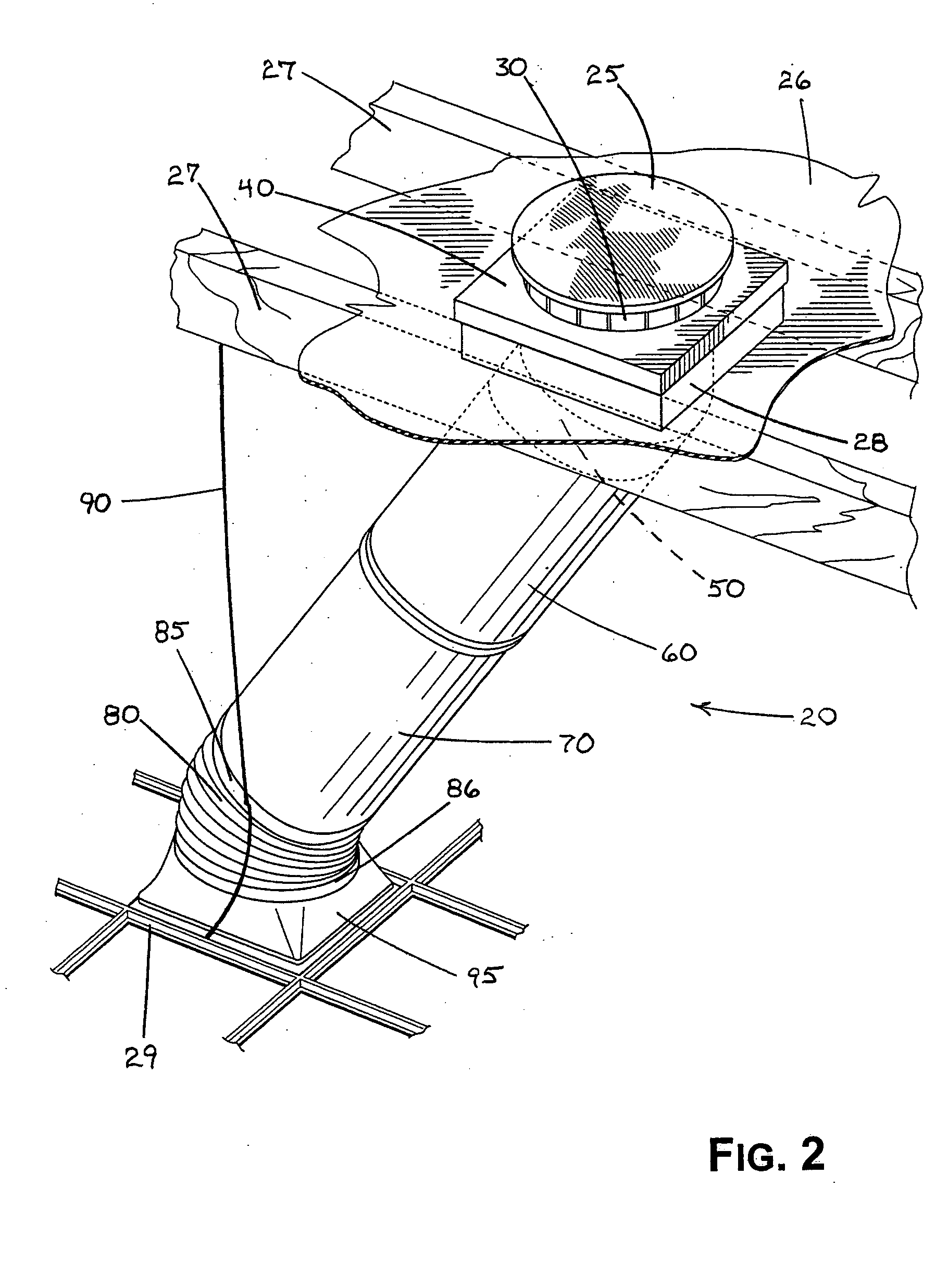
Another problem is caused by the fact that buildings in which such tubular skylights are to be installed often have pitched roofs.
While several devices that have already been commercialized purport to depict a straightforward and simple alignment between the exterior dome and the interior diffuser panel, experience in the field teaches that precise measurement, good alignment, and efficient
light transmission can be difficult to achieve with such devices.
Reasons for this preference are varying, but include concern that indoor work in
retrofitting efforts to existing buildings is intrusive to building occupants, may be crowded with other tradesmen engaged in other tasks in new construction installations, risks collateral damage from tools, ladders, and the like to interior, fine-finished surfaces such as floors and walls, and so forth.
A fourth problem has been discovered with specific reference to installation of tubular skylights in new construction.
However, the device in the '713 patent requires, at a minimum, installation of the tubular skylight after installation of the ceiling
joist, and makes no allowance for installations in buildings having no ceiling joists.
Three other problems have been identified with reference to existing tubular skylight systems, and these three problems do not relate to the method or timing of installation but instead to the function and continued integrity of the skylight after installation.
First, governmental authorities in some jurisdictions have enacted
building code requirements that require devices such as tubular skylights to withstand certain earthquake forces.
Skylight assemblies in which the light tubes or other components are supported by the ceiling cannot satisfactorily meet such requirements.
A second functional problem has been discovered with regard to
thermal expansion and contraction of the skylight assembly and / or the building in which the assembly is installed.
Moreover, mechanical compression of an installed skylight assembly may result from workers upon the roof of a building, the weight of whom may tend to deflect the roof downward.
Thermal expansion of the skylight assembly, or compression of the roof sheathing by workers upon the roof, might cause the diffuser panel at the interior ceiling to protrude from the plane in the ceiling, or may break loose attached components of the skylight assembly, either result being undesirable.
Alternatively, either effect may cause the structure of the exterior dome to protrude upward from its installed position upon the roof, breaking loose weatherproofing that would otherwise seal the installed assembly.
Finally, another problem has been encountered with the use of tubular skylights in applications in which a rectangular diffuser panel is used at the interior ceiling, such as with a suspended ceiling.
However, adapting from such a generally circular cross-sectional light tunnel to a rectangular diffuser panel has been found to cause differential lighting upon the diffuser panel.
Sometimes known as “hot spots,” in such applications the diffuser panel tends to have regions of greater
light intensity and regions of lesser
light intensity, a phenomenon considered to be undesirable by the consuming public.


