
Cooling system diagnostic system apparatus and method

a cooling system and diagnostic system technology, applied in lighting and heating apparatus, space heating and ventilation control systems, heating types, etc., can solve the problems of increasing the cost of electronics and sensors, increasing so as to improve the diagnostic results and reduce the cost of maintenance and repair. , the effect of efficient service of the air-conditioning system

Inactive Publication Date: 2005-08-04
EMERSON CLIMATE TECH INC
View PDF46 Cites 110 Cited by
  • Summary
  • Abstract
  • Description
  • Claims
  • Application Information

AI Technical Summary

Benefits of technology

The system enables more accurate and efficient diagnosis and repair by monitoring comprehensive system parameters, reducing misdiagnosis and training costs, and ensuring continuous updates through wireless connectivity, thus addressing the limitations of prior art service units.

Problems solved by technology

However, the costs associated with these electronics and the sensors is too much for cost sensitive systems like residential air-conditioning systems and small commercial installations.
The problems associated with depending upon the skill and knowledge of the service technician is expected to compound in the future due in part to the introduction of many new refrigerants.
Thus, the large experience that the technicians have gained on current day refrigerants will not be adequate for the air-conditioning systems of the future.
This leads to a high cost for training and a higher incident of misdiagnosing which needs to be addressed.
The problem of accurate diagnosis is complicated by the large number of different air-conditioning systems in the marketplace.
While each air-conditioning system includes a basic air-conditioning cycle, the various systems can include components and options that complicate the diagnosis for the system as a whole.
Accordingly, with these prior art service units, misdiagnosis can occur, resulting in improperly repaired systems and in excessive time to complete repairs.
Although service manuals are available to assist the technician in diagnosing and repairing the air-conditioning systems, their use is time-consuming and inefficient.
In addition, the large number of manuals require valuable space and each manual must be kept up to date.
The systems that monitor only the high and low pressure side pressures of the air-conditioning system are thus inherently limited in their diagnostic ability.

Method used


Image

  • Cooling system diagnostic system apparatus and method
  • Cooling system diagnostic system apparatus and method
  • Cooling system diagnostic system apparatus and method

Examples


Embodiment Construction

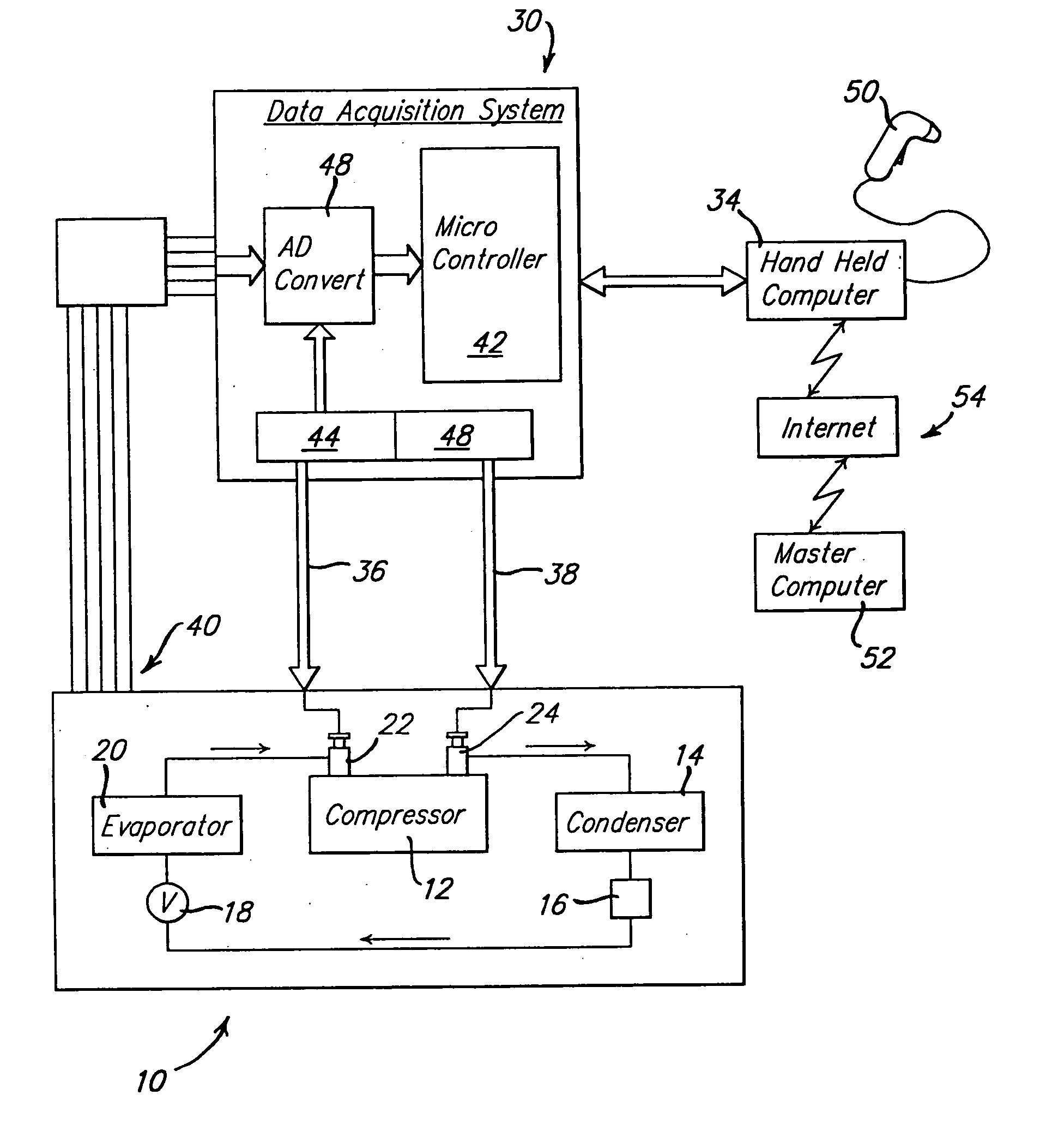
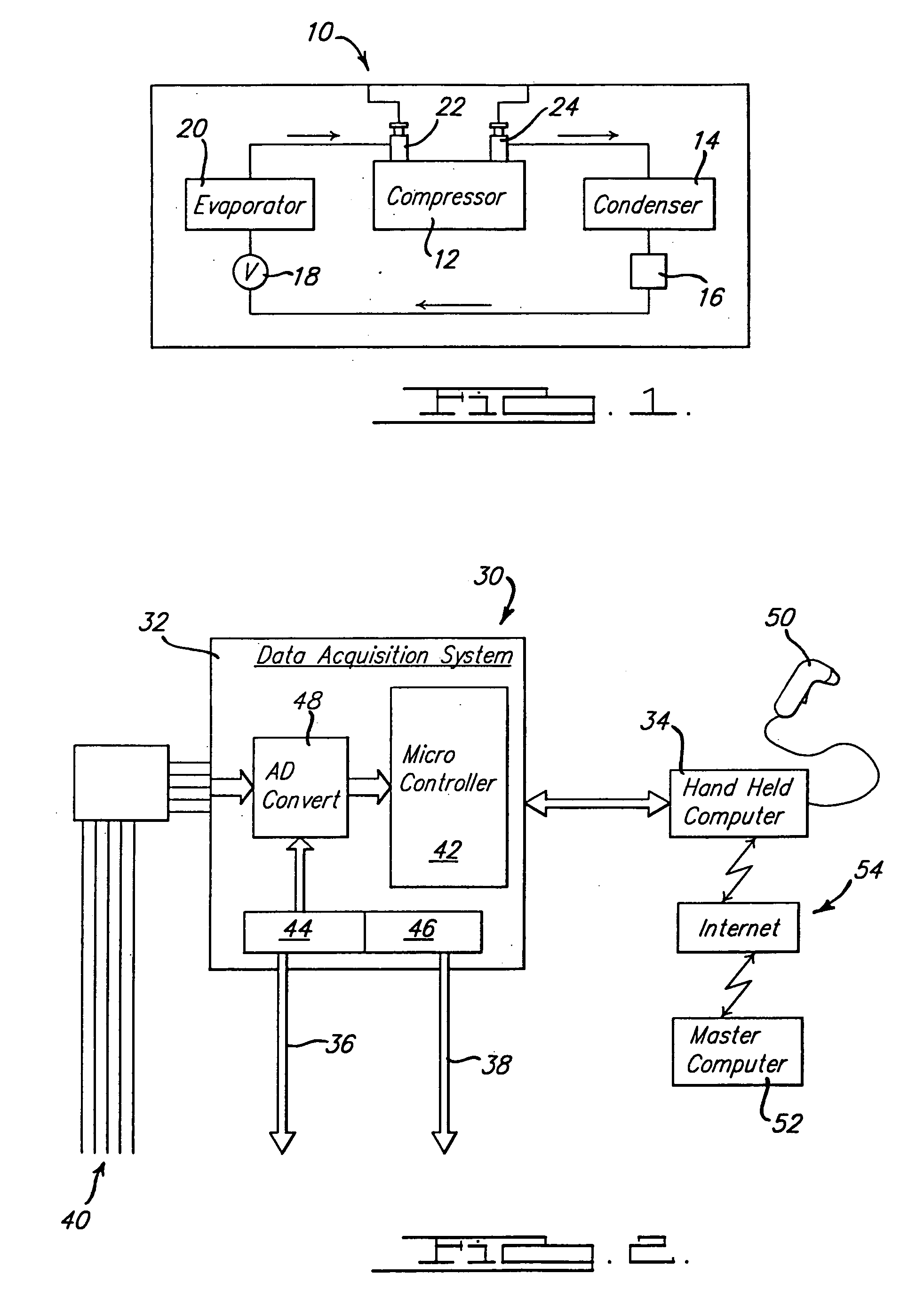
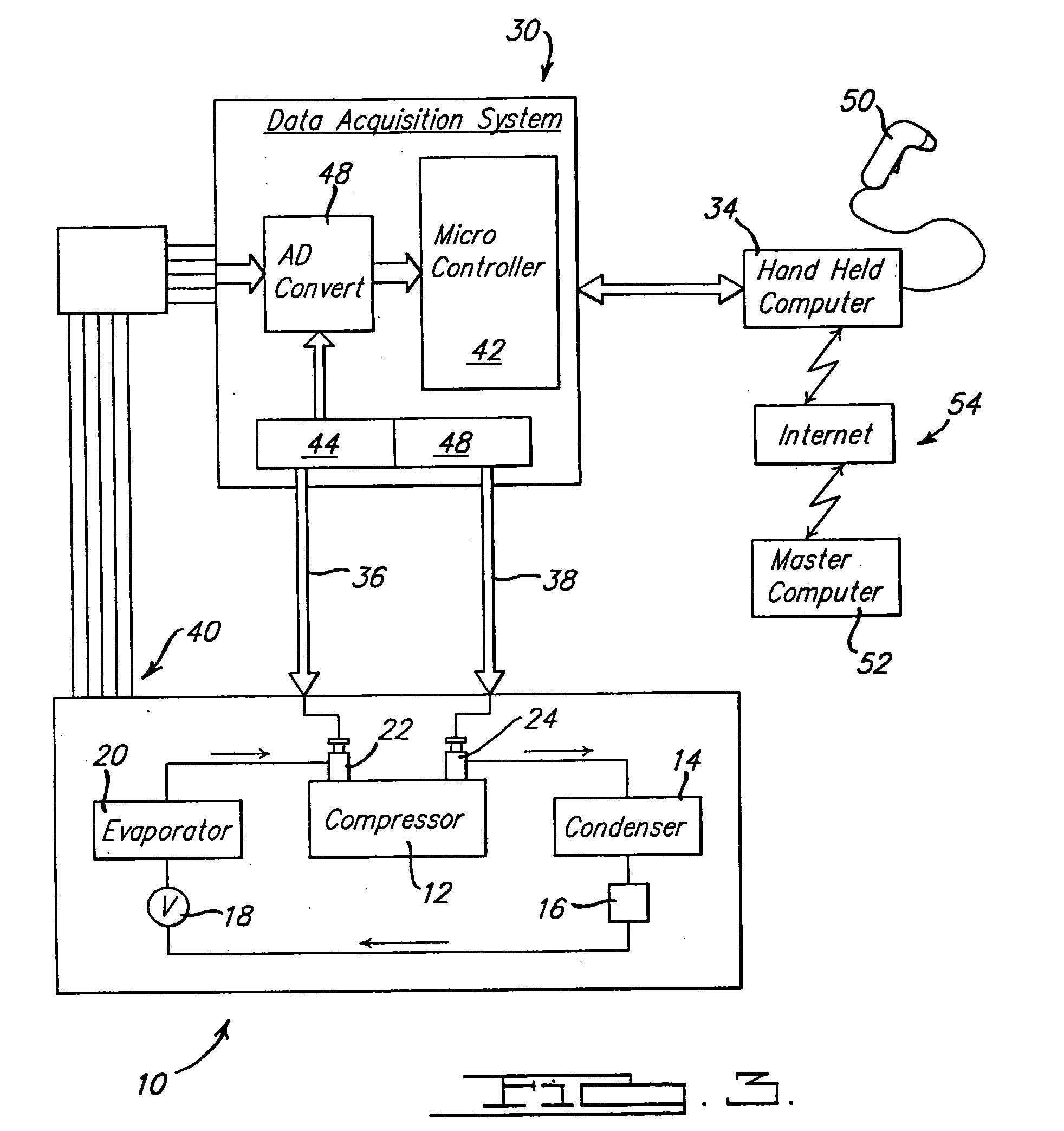
[0014] Referring now to the drawings in which like reference numerals designate like or corresponding parts throughout the several views, there is shown in FIG. 1 an air-conditioning system for use with the service system in accordance with the present invention and which is designated generally by the reference numeral 10. Air-conditioning system 10 comprises a compressor 12 which compresses refrigerant gas and delivers it to a condenser 14 where the compressed gas is converted to a liquid. Condensor 14 discharges through a sight glass 16 which provides visual observation of the fill level of refrigerant in the system during operation. Sight glass 16 also normally includes a reservoir for storing liquid refrigerant under conditions of large load fluctuations on the system, and includes a high-pressure filter and desiccant to trap and hold any moisture or solid particles which may be present in the system. From sight glass 16, the refrigerant is delivered through an expansion valve ...


PUM


Abstract

An apparatus and method for diagnosing a cooling system includes a first sensor operable to detect a compressor supply amperage, a second sensor operable to detect a compressor supply voltage, and a third sensor operable to detect a compressor rotational speed. A controller in communication with the first, second and third sensors communicates with a computer that compares at least two of the supply amperage, supply voltage and rotational speed with normal operating parameters, and outputs a diagnosis.

Description

CROSS-REFERENCE TO RELATED APPLICATIONS [0001] This application is a continuation of U.S. patent application Ser. No. 10 / 844,607 filed on May 12, 2004, which is a continuation of U.S. patent application Ser. No. 10 / 280,774 filed on Oct. 25, 2002 (now U.S. Pat. No. 6,823,680), which is a continuation of U.S. patent application Ser. No. 10 / 012,631 filed on Dec. 7, 2001 (now U.S. Pat. No. 6,560,976), which is a continuation of U.S. patent application Ser. No. 09 / 721,594 filed on Nov. 22, 2000 (now U.S. Pat. No. 6,324,854), which are incorporated herein by reference.FIELD OF THE INVENTION [0002] The present invention relates generally to an apparatus and a method for servicing a cooling system. BACKGROUND AND SUMMARY OF THE INVENTION [0003] Several air-conditioning service units are available to assist a trained technician in servicing an air-conditioning system. Some prior art units are adapted to be connected to the high- and low-pressure sides of the air-conditioning system and these...

Claims


Application Information

Patent Timeline
Patent Type & Authority Applications(United States)
IPC IPC(8): F24F1/00F24F11/00F25B49/00
CPCF24F11/0086F24F2011/0043F25B2500/06F25B49/005F24F2011/0091F24F11/30F24F2140/12F24F11/52F24F11/38F24F11/88F24F1/00
Inventor JAYANTH, NAGARAJ
Owner EMERSON CLIMATE TECH INC
Learn More