Piston/combustion chamber configurations for enhanced ci engine performace

a technology of combustion chamber and engine, which is applied in the direction of combustion engines, cylinders, machines/engines, etc., can solve the problems of difficult control of all variables, difficult to predict the effect of different chamber configurations, and large squish region, so as to achieve significant emissions reduction

Inactive Publication Date: 2005-08-04
WISCONSIN ALUMNI RES FOUND
View PDF15 Cites 15 Cited by
  • Summary
  • Abstract
  • Description
  • Claims
  • Application Information

AI Technical Summary

Benefits of technology

[0013] The invention, which is defined by the claims set forth at the end of this document, is directed to methods and apparata which provide piston designs (and therefore combustion chamber designs) which result in significant emissions reduction in HSDI engines while maintaining or reducing BSFC. A piston and combustion chamber in accordance with the invention includes a piston face bounded by a piston side, with a face perimeter region extending inwardly from the piston side and preferably being oriented at least substantially perpendicular to the piston side. An open bowl descends from the face perimeter region, with the bowl including a first depressed region descending from the face perimeter region at a first angle (the first angle being measured with respect to the face perimeter region); a second depressed region descending from the first depressed region at a second angle which is greater (i.e., steeper) than the first angle (the second angle also being measured with respect to the face perimeter region); and a bowl floor extending from the second depressed region, preferably across the center of the piston. The first angle at which the first depressed region descends from the face perimeter region is preferably acute, more preferably less than 30 degrees, whereas the second angle at which the second depressed region is preferably greater than 45 degrees. The face perimeter region is preferably rather large (e.g., occupying 40% or more of the piston face, as measured from a plane perpendicular to the axis of the piston) so as to define a relatively large squish region within the combustion chamber. Additionally, it is also preferred that a re-entrant bowl design be avoided, i.e., the first and second depressed regions do not slope outwardly towards the piston side as they extend downwardly towards the bowl floor.
[0014] The piston travels within a cylinder to define the combustion chamber between the piston face and the cylinder head of the cylinder. A fuel injector is situated within the combustion chamber, and is configured to inject a fuel plume along a direction oriented above the bowl floor and below the face perimeter region, more preferably toward the first depressed region and at or adjacent to an intermediate edge defined between the first and second depressed regions.

Problems solved by technology

Unfortunately, measures which reduce NOx tend to increase particulate emissions, and measures which reduce particulates tend to increase NOx emissions, resulting in what is often termed the “soot-NOx tradeoff”.
This requires considerable expense and complexity, since typically additional fuel must be mixed and ignited in the exhaust stream in order to oxidize the accumulated particulate deposits.
One difficulty with achieving premixed combustion is the difficulty in controlling all variables needed for its achievement, especially across a wide range of operating speeds and loads.
Owing to the number of variables involved in engine performance, and the interaction between these variables, the effect of different chamber configurations is not easily predicted.
While prior studies have resulted in improvements in engine performance, there is still significant room for improvement in combustion chamber designs which result in reduced emissions with reasonable BSFC (brake specific fuel consumption, i.e., fuel consumption per unit of useful output power).

Method used


Image

  • Piston/combustion chamber configurations for enhanced ci engine performace
  • Piston/combustion chamber configurations for enhanced ci engine performace
  • Piston/combustion chamber configurations for enhanced ci engine performace

Examples


Embodiment Construction

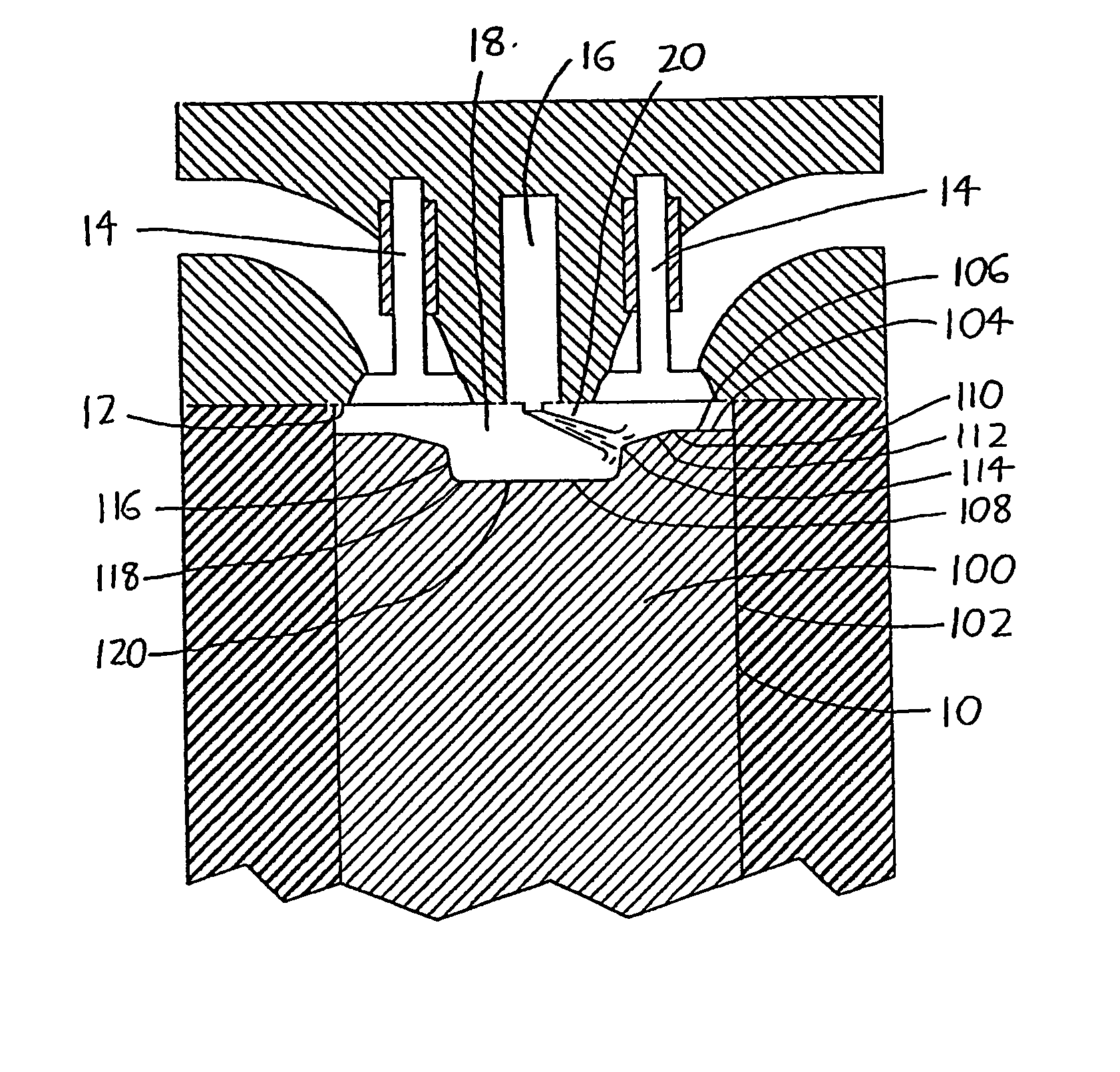
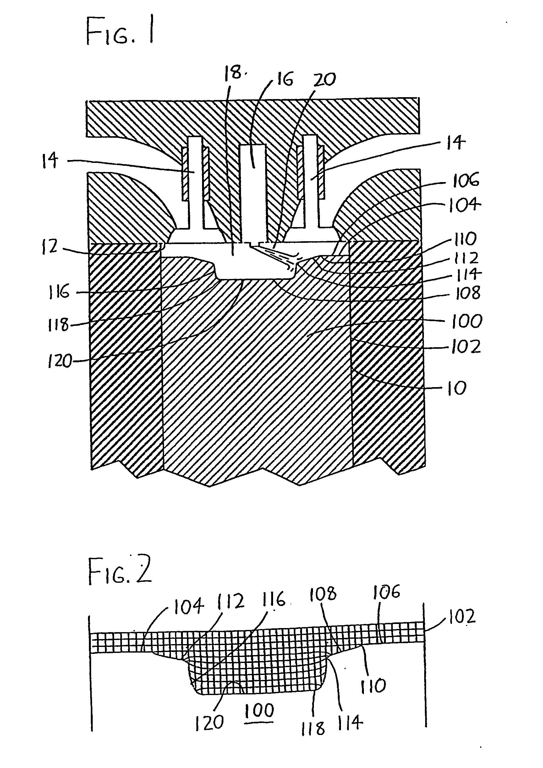
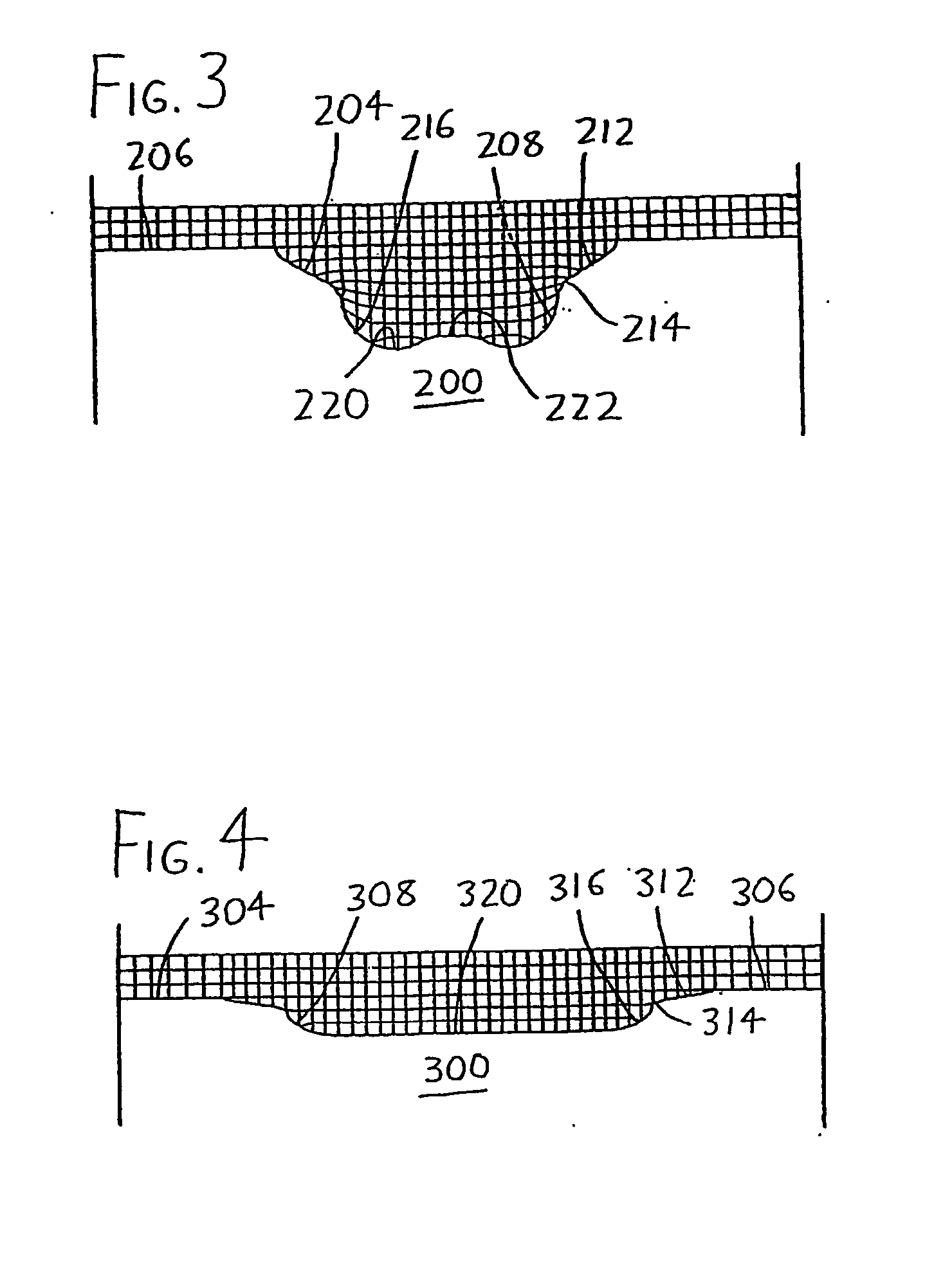
[0020] Preferred versions of the piston and combustion chamber designs of the invention will now be described with reference to the piston face configurations of FIGS. 2-4, any of which may be utilized in a diesel engine cylinder and combustion chamber such as the one illustrated in FIG. 1 (which utilizes a piston 100 having the piston face configuration in FIG. 2). The cylinder is defined by cylinder walls 10 along which the piston 100 slides, with the piston having a piston side 102 surrounding a piston face 104. During engine operation, the piston face 104 alternately approaches and retreats from the cylinder head 12, wherein intake and exhaust valves 14 are provided along with an injector 16. The space between the piston face 104, cylinder walls 10, and cylinder head 12 defines the combustion chamber 18 wherein the combustion event occurs after the injector 16 injects a fuel plume 20 into the combustion chamber 18. Note in FIG. 1, the injector 16 is shown injecting one fuel plum...


PUM


Abstract

Piston face (104, 204, 304) and combustion chamber (18) designs for use particularly in HSDI (high speed direct injection) diesel engines include an open bowl (108 208, 308) characterized by a large face perimeter region (106, 206, 306) on the piston face (104, 204, 304), and a bowl (18) defined by a first depressed region (112, 212, 312) gently sloping radially inwardly from the face perimeter region (106, 206, 306) and a second depressed region (116, 216, 316) sharply sloping radially inwardly from the first depressed region (112, 212, 312) to the bowl floor (120, 220, 320). Injection is preferably directed towards an intermediate edge which is well-defined between the first and second depressed regions, resulting in portions of the injected fuel plume being directed to both the squish regions and the portion of the bowl situated below the intermediate edge. The designs promote premixed or MK (Modulated Kinetics) combustion, with a concomitant reduction in soot and nitrous oxides (NOx) emissions while maintaining or enhancing brake specific fuel consumption.

Description

CROSS-REFERENCE TO RELATED APPLICATIONS [0001] This application claims priority under 35 USC §119(e) to U.S. Provisional Patent Application 60 / 387,865 filed 11 Jun. 2002, the entirety of which is incorporated by reference herein.STATEMENT REGARDING FEDERALLY SPONSORED RESEARCH [0002] This invention was made with United States government support awarded by the following agencies: [0003] U.S. Department of Energy (DOE) Grant No. DE-FG04-99AL66269 The United States has certain rights in this invention.FIELD OF THE INVENTION [0004] This disclosure concerns an invention relating generally to piston and / or combustion chamber configurations which allow reduction of emissions and fuel consumption in internal combustion engines, and more specifically to piston and / or combustion chamber configurations which provide emissions reduction in compression ignition (CI or diesel) engines. BACKGROUND OF THE INVENTION [0005] Common pollutants arising from the use of compression ignition (CI or diesel)...

Claims


Application Information

Patent Timeline
Patent Type & Authority Applications(United States)
IPC IPC(8): F02B1/12F02B3/06F02B23/06F02F1/24
CPCF02B1/12F02B3/06F02B23/0621F02B23/0636Y02T10/123F02B23/0696F02B2275/14F02F2001/247Y02T10/125F02B23/0651Y02T10/12
Inventor WICKMAN, DAVID DARINREITZ, ROLF DENEYS
Owner WISCONSIN ALUMNI RES FOUND
Why Eureka
Try Eureka