Spot welding apparatus

a spot welding and apparatus technology, applied in the field of spot welding apparatus, can solve the problems of reducing the reliability of spot welding, workpieces cannot be contacted, etc., and achieve the effects of improving spot welding reliability, efficient heating, and enhancing spot welding efficiency

Active Publication Date: 2005-08-04
SUBARU CORP
View PDF5 Cites 6 Cited by
  • Summary
  • Abstract
  • Description
  • Claims
  • Application Information

AI Technical Summary

Benefits of technology

[0022] According to the present invention, the portions of the workpieces to be welded with which each of the electrodes is brought into contact are induction-heated by the high frequency heating means having the heating coil corresponding to each of the electrodes, and therefore, for example, even if opening is generated between the workpieces made of high tension steel, the workpieces can be sufficiently deformed by application of pressure by the electrodes, whereby the workpieces to be welded can brought in contact with each other to be firmly welded. Thus reliability of the spot welding can be improved.
[0023] According to the invention of the embodiment (1), the control of operation of the high frequency heating means is carried out based on a value of the welding current, and hence efficiency of the spot welding can be enhanced.
[0024] According to the invention of the embodiment (2), the heat operation is not carried out by the high frequency heating means when the value of the welding current exceeds a predetermined standard value, and current value and / or frequency number of a high frequency current transmitted to the heating coil is controlled based on the value of the welding current and type of material of the workpieces when the value of the welding current is not more than a predetermined standard value. Thus, the workpieces can be efficiently heated only in case of requiring heating, whereby the spot welding can be efficiently carried out.
[0025] According to the invention of the embodiment (3), each of the heating coils can be driven in a direction parallel to a moving direction of the corresponding electrode, and the driving is controlled based on the value of the welding current. Hence, the welding portions can be heated at an adequate position.
[0026] According to the invention of the embodiment (4), each of the heating coils is allowed to move to a predetermined position in a rear of the workpieces when the value of the welding current exceeds a predetermined standard value, and each of the heating coils is allowed to move to a predetermined heating position in the vicinity of the workpieces when the value of the welding current is not more than a predetermined standard value. Hence, the workpieces can be efficiently heated only in case of requiring heating, whereby the spot welding can be efficiently carried out.
[0027] According to the invention of the embodiment (5), each of the heating coils is allowed to move together with the corresponding electrode, and hence the constitution of the apparatus can be made simple.

Problems solved by technology

In the spot welding apparatus of the above-mentioned publication, however, the preheating of the workpieces is carried out by application of the welding current, and consequently there are some cases where the workpieces cannot be contacted each other in the portions which should be welded under application of pressure by the electrodes when the welding current for the preheating flows far from the welding portions (portions to be welded) owing to existence of opening between the workpieces.
Thus, the spot welding apparatus disclosed in the above-mentioned publication does not occasionally bring about attainment of the expected results to reduce reliability of the spot welding.

Method used


Image

  • Spot welding apparatus
  • Spot welding apparatus
  • Spot welding apparatus

Examples


Embodiment Construction

[0031] Embodiments of the spot welding apparatus according to the present invention are explained by reference of FIGS. 1 and 2 below.

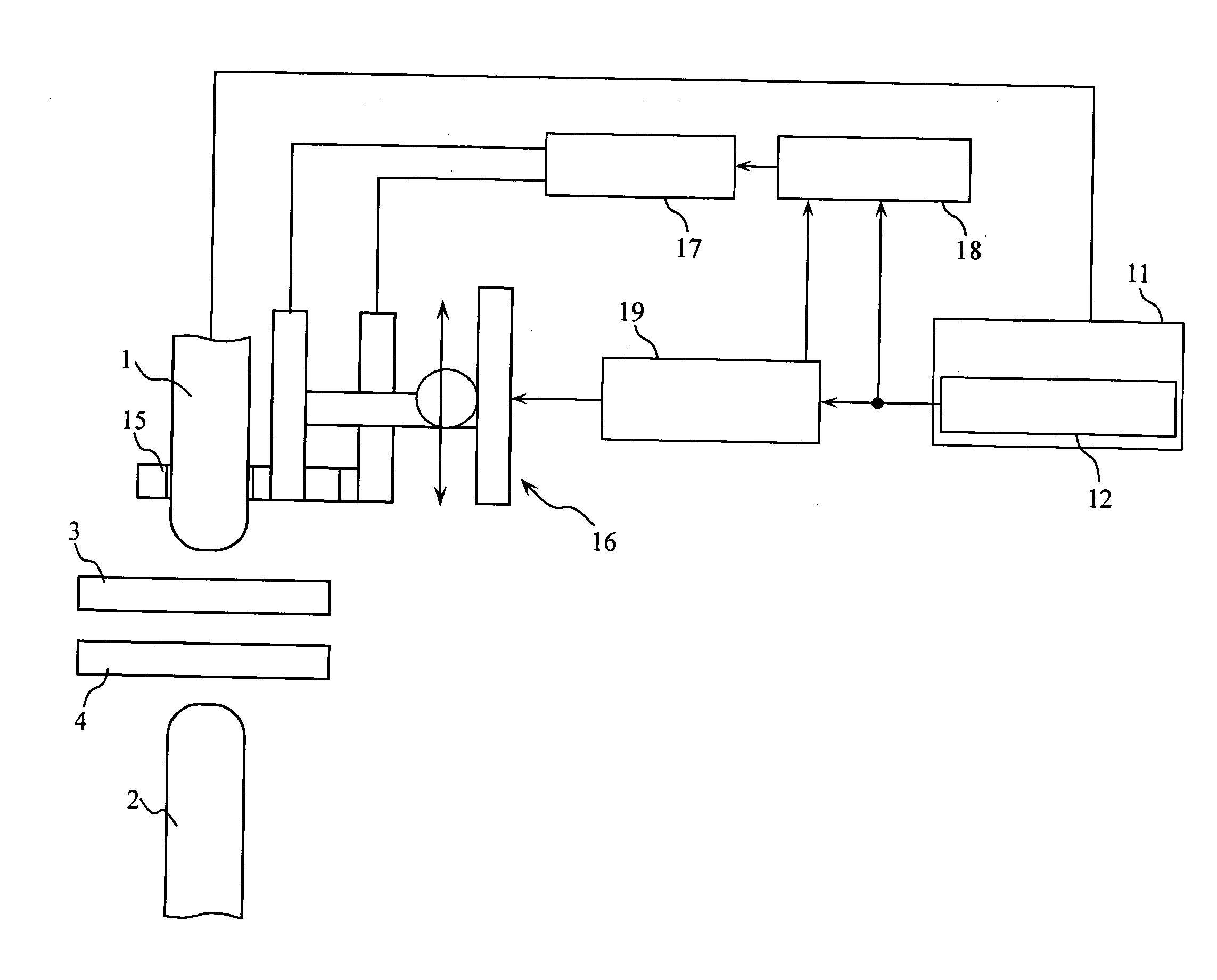
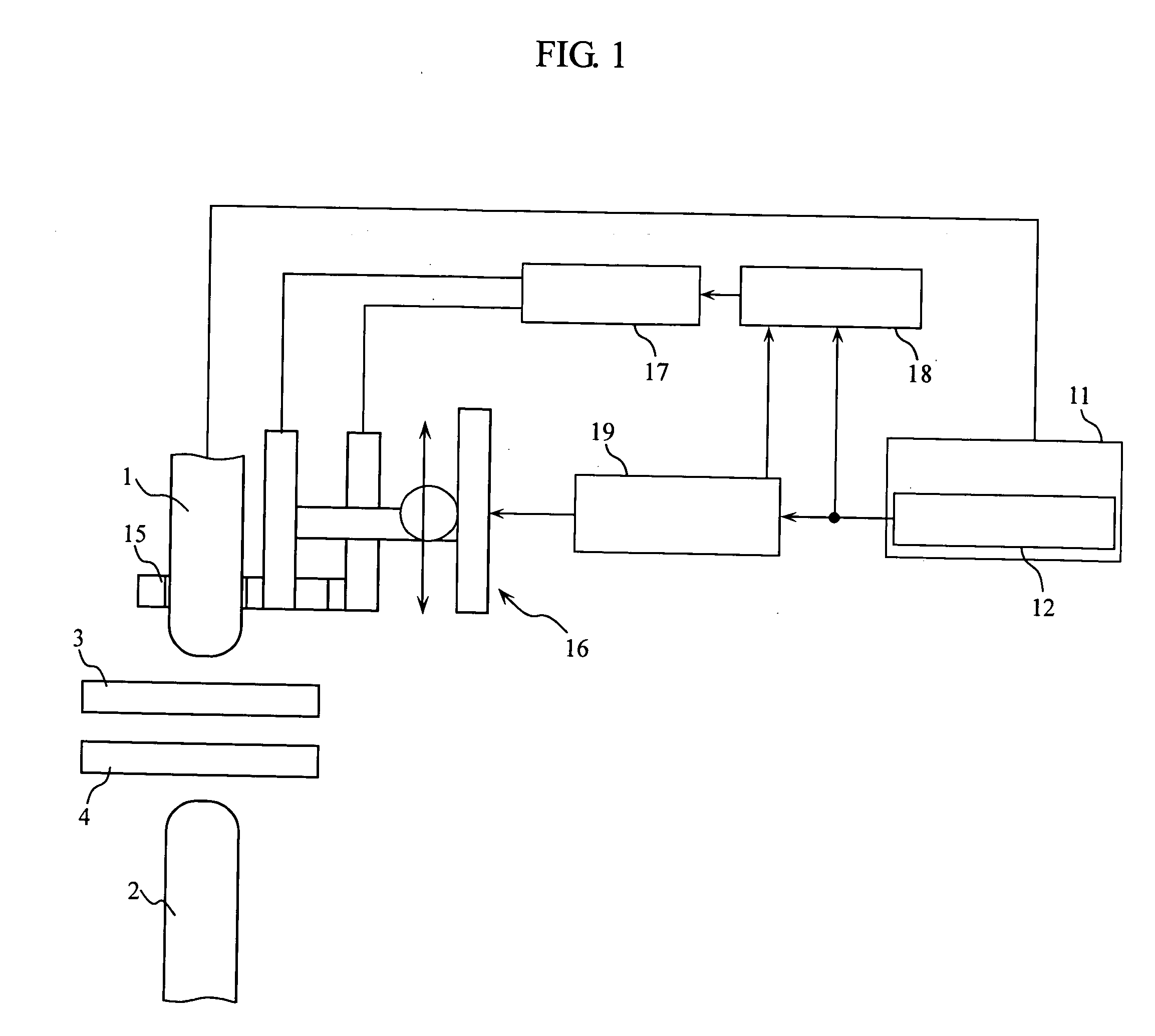
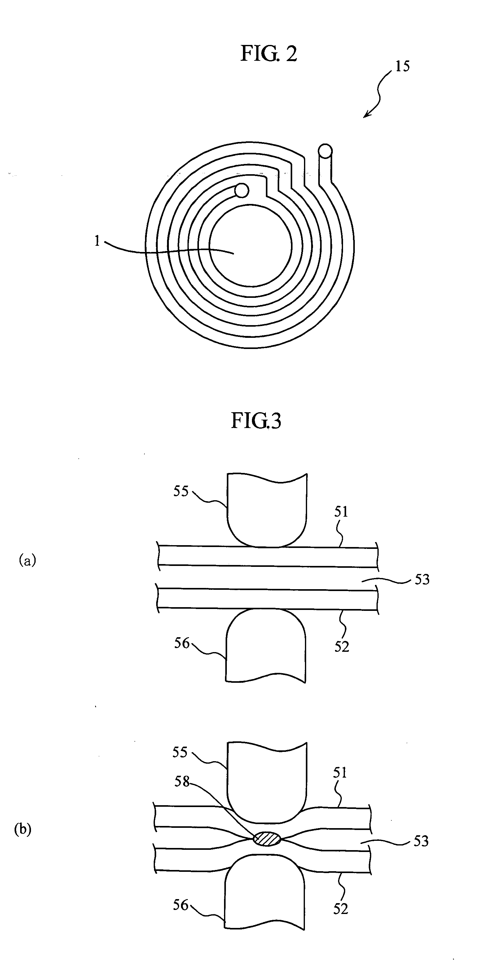
[0032]FIG. 1 is a view showing the constitution of a feature of the spot welding apparatus according to the present invention. FIG. 2 is a plane view of the heating coil illustrated in FIG. 1.

[0033] In a spot welding apparatus using a servo-gun, a pair of electrodes 1, 2 are driven using a servomotor (not shown) and workpieces 3, 4 are put between the edges of the electrodes 1, 2 under application of pressure, and under this condition, welding current is applied between the electrodes 1, 2 to spot weld the workpieces 3, 4. In the spot welding apparatus according to the embodiment of the invention, the servo-gun control apparatus 11 controlling the drive of the electrodes 1, 2 is provided with a welding current detecting circuit (i.e., welding current detecting means) 12 which detects a welding current flowing between the electrodes 1 and 2.

[0034] F...


PUM

PropertyMeasurementUnit
temperatureaaaaaaaaaa
time periodaaaaaaaaaa

Abstract

A spot welding apparatus for spot welding superposed workpieces by putting the superposed workpieces 3, 4 between a pair of electrodes 1, 2 and applying a welding current between the electrodes under application of pressure, the apparatus having heating coils 15 wound on each of the electrodes 1, 2, and being provided with high frequency heating means 17 for induction-heating welding portions of the workpieces contacted by the electrodes. The spot welding apparatus is capable of firmly spot welding workpieces made of high tension steel even if there is opening between the workpieces.

Description

CROSS REFERENCE TO RELATED APPLICATIONS AND INCORPORATION BY REFERENCE [0001] This application based upon and claims the benefit of priority from the prior Japanese Patent Application No. 2004-021718, filed on Jan. 29, 2004; the entire content of which is incorporated herein by reference. BACKGROUND OF THE INVENTION [0002] 1. Field of the Invention [0003] The present invention relates an apparatus for spot welding superposed workpieces by putting the superposed workpieces between a pair of electrodes and applying a welding current between the electrodes under application of pressure. [0004] 2. Description of the Related Art [0005] In a spot welding apparatus, the superposed workpieces are put between edges of a pair of electrodes and pressed between the electrodes under application of a welding current (electric current) whereby the superposed workpieces are spot welded. In case material of the workpieces is apt to be deformed by the application of pressure between the electrodes 55...

Claims


Application Information

Patent Timeline
Patent Type & Authority Applications(United States)
IPC IPC(8): H05B3/00B23K11/11B23K13/01H05B3/03H05B6/10H05B6/36H05B11/00
CPCB23K11/115
Inventor TAKAHASHI, KUNIAKISHIN, KENEI
Owner SUBARU CORP
Why Eureka
Try Eureka