Selector circuit for power management in multiple battery systems

a power management and selector circuit technology, applied in the direction of safety/protection circuits, charging/discharging, transportation and packaging, etc., can solve the problems of inconvenient operation, inability to independently ascertain selector circuits, and inability to accept control signals from host power management units

Inactive Publication Date: 2005-08-04
O2 MICRO INT LTD
View PDF0 Cites 41 Cited by
  • Summary
  • Abstract
  • Description
  • Claims
  • Application Information

AI Technical Summary

Problems solved by technology

In addition, such selector circuits typically cannot independently ascertain, correct, and notify other components in the power supply block of a power crises condition.
In addition, such selector circuits are not configured to accept control signals from an associated host power management unit.

Method used


Image

  • Selector circuit for power management in multiple battery systems
  • Selector circuit for power management in multiple battery systems
  • Selector circuit for power management in multiple battery systems

Examples


Embodiment Construction

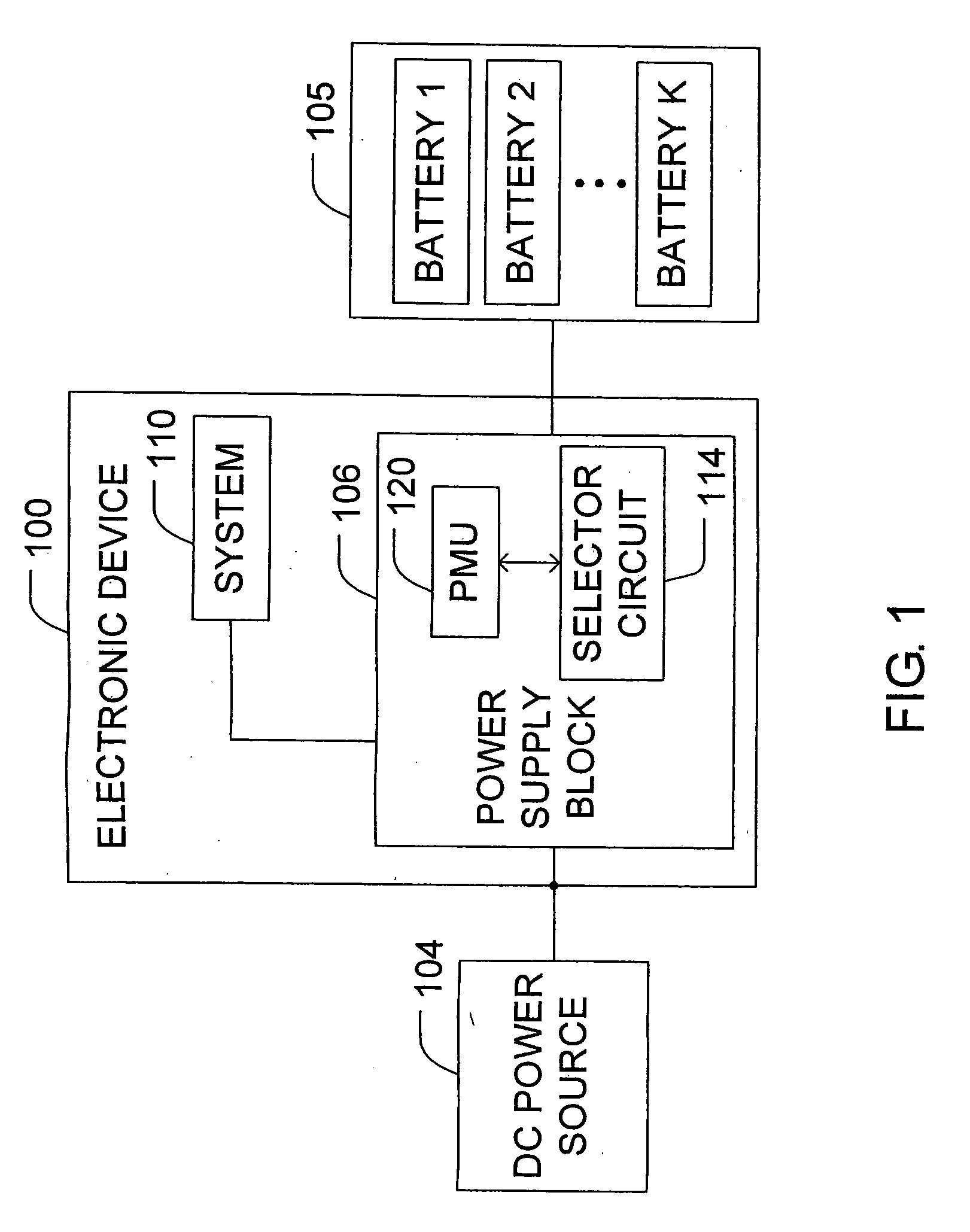
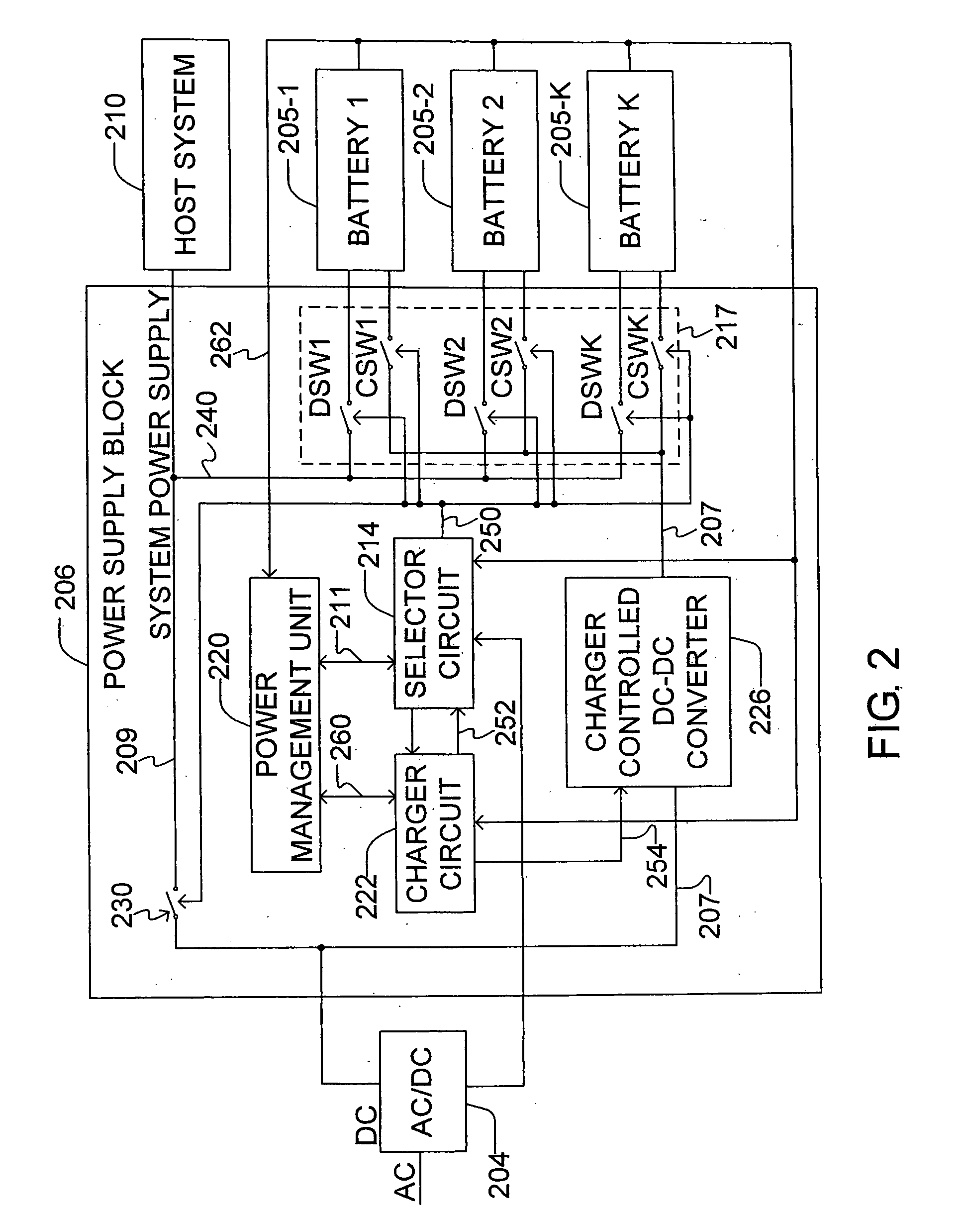
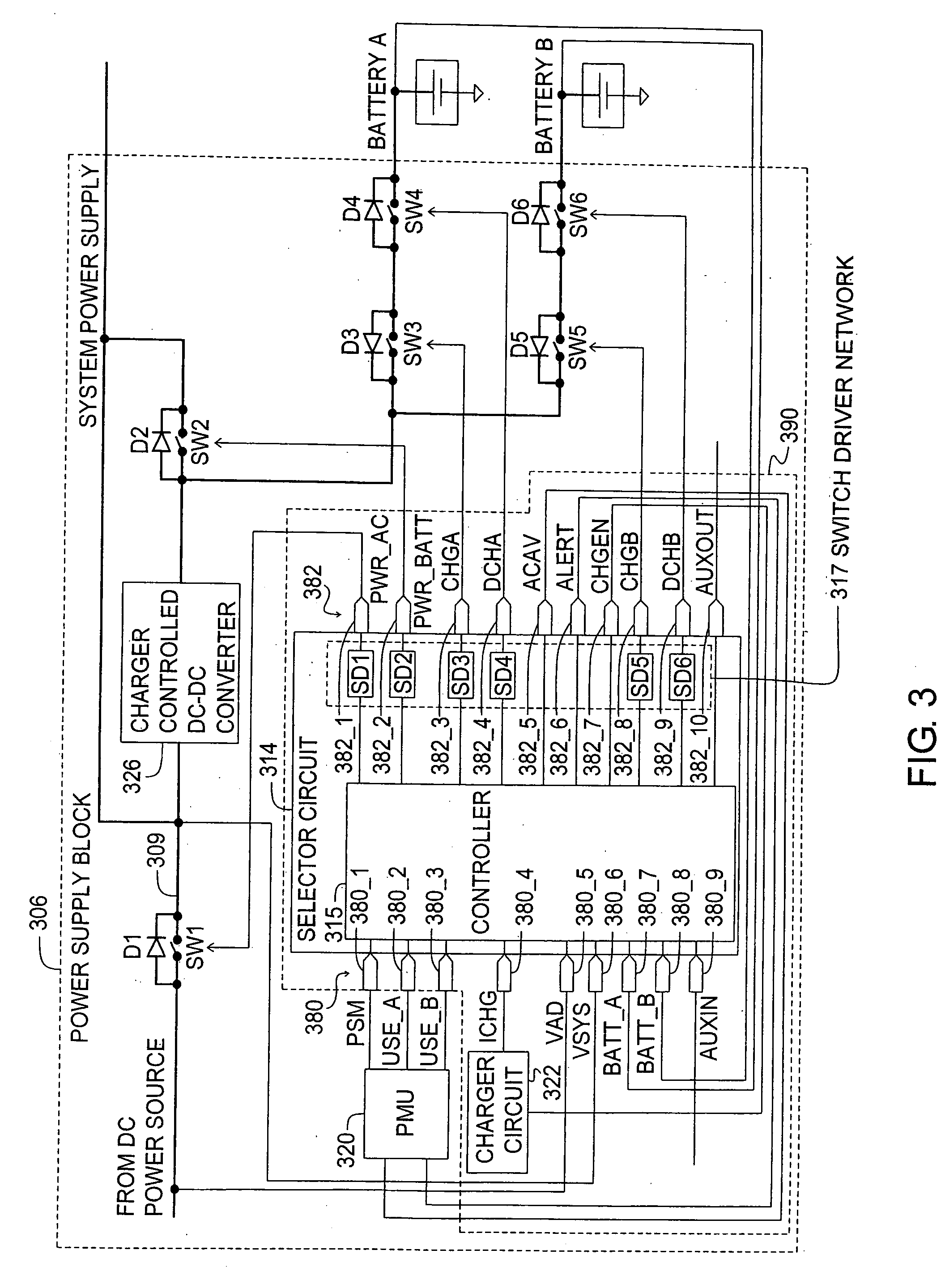
[0017] Turning to FIG. 1, a simplified block diagram of an electronic device 100 capable of being powered from any number of power sources 104, 105 is illustrated. Such power sources may include a plurality of batteries 105 and a DC power source 104. The batteries 105 may further be rechargeable batteries of various types such as lithium-ion, nickel-cadmium, nickel-metal hydride batteries, or the like. The electronic device 100 may be any variety of devices known in the art such as portable electronic devices (laptop computers, cell phones, pagers, personal digital assistants, camcorders, digital cameras, radio cassette players, and the like), an electric powered vehicle, power tools, etc. that may be powered from either power source 104, 105 in various instances.

[0018] If the electronic device 100 is a laptop computer it would include a variety of components known to those skilled in the art which are not illustrated in FIG. 1. For example, the laptop may include an input device f...


PUM


Abstract

A selector circuit configured to select among a DC power source and a plurality of batteries for an electronic device. The selector circuit is responsive to an output signal from an associated power management unit. The selector circuit is further configured to permit parallel operation of two or more of the batteries. The selector circuit may further act to independently verify power conditions and override instructions from the PMU in certain instances to enhance power supply safety and battery life such as by preventing inter battery current flow from a higher potential battery to a lower potential battery coupled in parallel.

Description

CROSS REFERENCE TO RELATED APPLICATIONS [0001] The present application is a Continuation of U.S. Nonprovisional application Ser. No. 10 / 649,394 filed Aug. 27, 2003, now U.S. Pat. No. ______, which itself is a continuation-in-part application of U.S. Nonprovisional application Ser. No. 10 / 364,228 filed Feb. 11, 2003, the teachings of which are both incorporated herein by reference, and claims the benefit of U.S. Provisional Application No. 60 / 484,635 filed Jul. 3, 2003, the teachings of which are also incorporated herein by reference.FIELD OF THE INVENTION [0002] The present invention relates to selector circuits and in particular to selector circuits for use with multiple battery systems. BACKGROUND OF THE INVENTION [0003] Selector circuits are typically utilized in a power supply block for various electronic devices. Such selector circuits are generally designed to select between a DC power source, e.g., an AC / DC adapter, and a rechargeable battery. In addition, in various electron...

Claims


Application Information

Patent Timeline
Patent Type & Authority Applications(United States)
IPC IPC(8): H02J7/00H02J7/34
CPCH02J7/0057H02J7/0068H02J7/34H02J2007/0059H02J7/0027H02M2001/0045Y02T10/7055H02J7/0013H02J7/0018H02J2007/0067H02J7/0031H02J7/0069H02J2207/20H02J7/0025Y02T10/70H02M1/0045
Inventor STANESTI, VLAD POPESCUNICULAE, MARIANBUCUR, CONSTANTIN
Owner O2 MICRO INT LTD
Why Eureka
Try Eureka