
Collision warning system and method for a motor vehicle

a technology for collision warning and motor vehicles, applied in wave based measurement systems, process and machine control, computation using non-denominational number representations, etc., can solve the problems of inability to calculate according to the foregoing formula, inability to meet the needs of the driver, and constant change of the distance and relative speed of the vehicl

Active Publication Date: 2005-08-04
WABCO EURO BVBA SPRL
View PDF9 Cites 39 Cited by
  • Summary
  • Abstract
  • Description
  • Claims
  • Application Information

AI Technical Summary

Benefits of technology

[0016] Generally speaking, in accordance with the present invention, an improved collision warning system and method for a motor vehicle are provided which improve over prior art systems and methods.
[0021] The system and method according to the present invention advantageously allow for the driver's reaction time to the generated warning signal. This reaction time is taken into consideration even when the driver is already braking. In this case, the driver's reaction time, that is, the time from normal braking to the required heavier or maximum braking, is shorter than the reaction time from no braking to braking since, in the first case, the driver's foot is already on the brake pedal.
[0022] A further advantage of the inventive system and method is that the calculations provided are physically correct and can therefore be used in every situation. Thus, the danger of a false alarm is reduced. All formulae are of sufficiently simple mathematical construction that they can be processed without problem even in the case of the limited computing power of microcontrollers with fixed-point arithmetic.

Problems solved by technology

The system described in U.S. Pat. No. 5,931,547 has the disadvantage, however, that the practical calculation yields a very long TTC, especially at short distances and at a relative speed close to zero.
In addition, the calculation according to the foregoing formula must also be regarded as impractical in highly dynamic driving situations, in which the distance and relative speeds of the vehicles are constantly undergoing rapid changes.
The system described in U.S. Pat. No. 6,604,042 does not provide for possible additional braking by the driver and also does not allow for the driver's reaction time.
Furthermore, no collision warning signal independent of the control action is generated for the driver.

Method used


Image

  • Collision warning system and method for a motor vehicle
  • Collision warning system and method for a motor vehicle
  • Collision warning system and method for a motor vehicle

Examples


Embodiment Construction

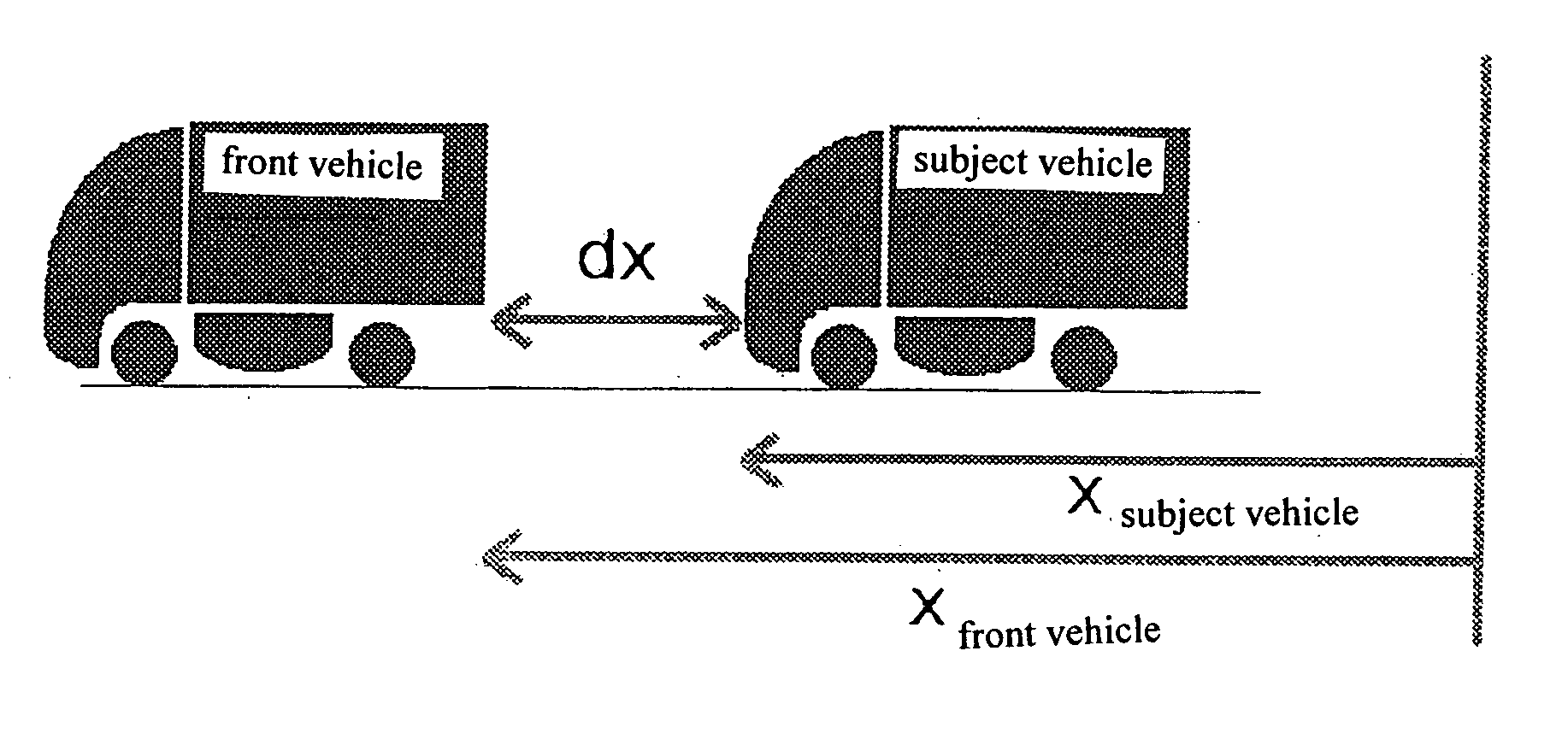
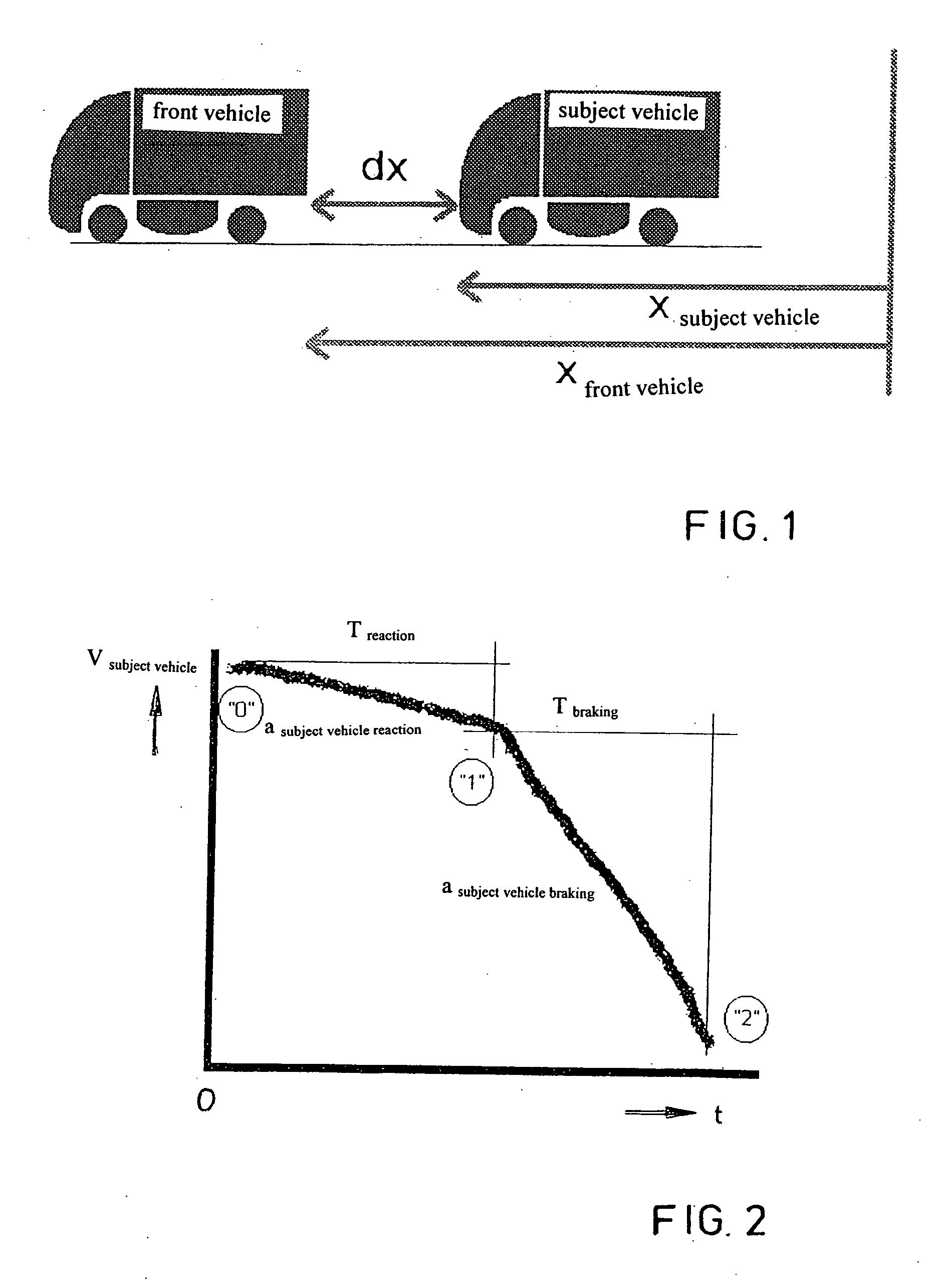
[0028] Referring to the drawing figures, FIG. 1 depicts a vehicle labeled “subject vehicle” and a vehicle labeled “front vehicle” traveling ahead of it. The “subject vehicle” is provided with the collision warning functionality according to the present invention.

[0029] The distance between the two vehicles at any given time is denoted by dx. The longitudinal coordinates of the two vehicles relative to an imaginary zero line are xsubject vehicle and xfront. By definition, xfront−xsubject vehicle=dx.

[0030] The possibility of transmitting a collision warning exists in principle for vehicles equipped with a forward looking sensor for checking the surroundings (such as the distance sensor of an ACC system). Such a warning can be audible, visual or tactile.

[0031] By means of the sensor, such as, for example, a RADAR sensor, the distance and / or speed relative to the vehicle traveling ahead can be established. The speed and acceleration or deceleration of the subject vehicle can be deter...


PUM


Abstract

A collision warning system and method for a motor vehicle. A measuring device in the vehicle is provided for measuring the distance dx to a second vehicle traveling ahead, the distance signal being delivered to an evaluation device in the first vehicle. The evaluation device continuously calculates a deceleration asubject vehicle demand, which is applied by the vehicle after expiration of a driver reaction time Treaction in order that a remaining distance dxremaining to the second vehicle traveling ahead can be maintained. If asubject vehicle demand exceeds an instantaneous deceleration that can be achieved by an adaptive cruise control (“ACC”) system, a system limit warning is transmitted, prompting the vehicle driver to brake with additional appropriate force. If asubject vehicle demand exceeds an assumed vehicle deceleration that can be generated by braking on the part of the driver, a collision warning signal is transmitted independently of the ACC system.

Description

BACKGROUND OF THE INVENTION [0001] The present invention is directed generally to a collision warning system and method for a motor vehicle. [0002] Modern road vehicles, particularly commercial vehicles, are increasingly being equipped with cruise control systems which enable a vehicle so equipped to achieve and maintain a constant cruising speed, which can be preset by the driver. The preset speed is maintained even when the vehicle is ascending or descending an incline. For this purpose, such cruise control systems are capable of opening or closing the vehicle throttle, as appropriate, or of actuating the vehicle retarder. [0003] Adaptive cruise control (“ACC”) or distance control systems can also measure the distance between a vehicle so equipped and vehicles traveling ahead, and maintain that distance constant. For this purpose, a distance measuring sensor is employed which can be designed as a RADAR or LASER sensor, for example. [0004] When the distance to the vehicle traveling...

Claims


Application Information

Patent Timeline
IPC IPC(8): B60K31/00B60K31/10B60T7/22B60W30/08B60W30/16
CPCB60K31/0008B60K31/107B60W30/16B60W30/09B60T7/22B60W2050/143
Inventor KITTERER, HARTMUTZIELKE, FRANKBREUER, KARSTENSANDKUHLER, DIRK
Owner WABCO EURO BVBA SPRL
Learn More