Broadcast receiving antenna and television broadcast receiver

Inactive Publication Date: 2005-08-04
PANASONIC CORP
View PDF5 Cites 1 Cited by
  • Summary
  • Abstract
  • Description
  • Claims
  • Application Information

AI Technical Summary

Benefits of technology

[0032] Therefore, it is possible to realize a digital television broadcast receiver that can change the antenna directiv

Problems solved by technology

Conventionally, in analog television broadcasting, in a case of receiving broadcast waves in a weak electric field, reduction in a receiving level by several dB greatly degrades the quality of pictures, or in a case of receiving broadcast waves in an urban area, unpleasant ghost pictures are generated due to waves which are reflected from buildings.
As described above, the magnetic current inducing type antenna that is considered as promising as a digital television broadcast receiving antenna is considered as suitable for the digital television broadcast receiving antenna, but a digital television broadcast receiving antenna employing such magnetic current inducing

Method used


Image

  • Broadcast receiving antenna and television broadcast receiver
  • Broadcast receiving antenna and television broadcast receiver
  • Broadcast receiving antenna and television broadcast receiver

Examples


embodiment 1

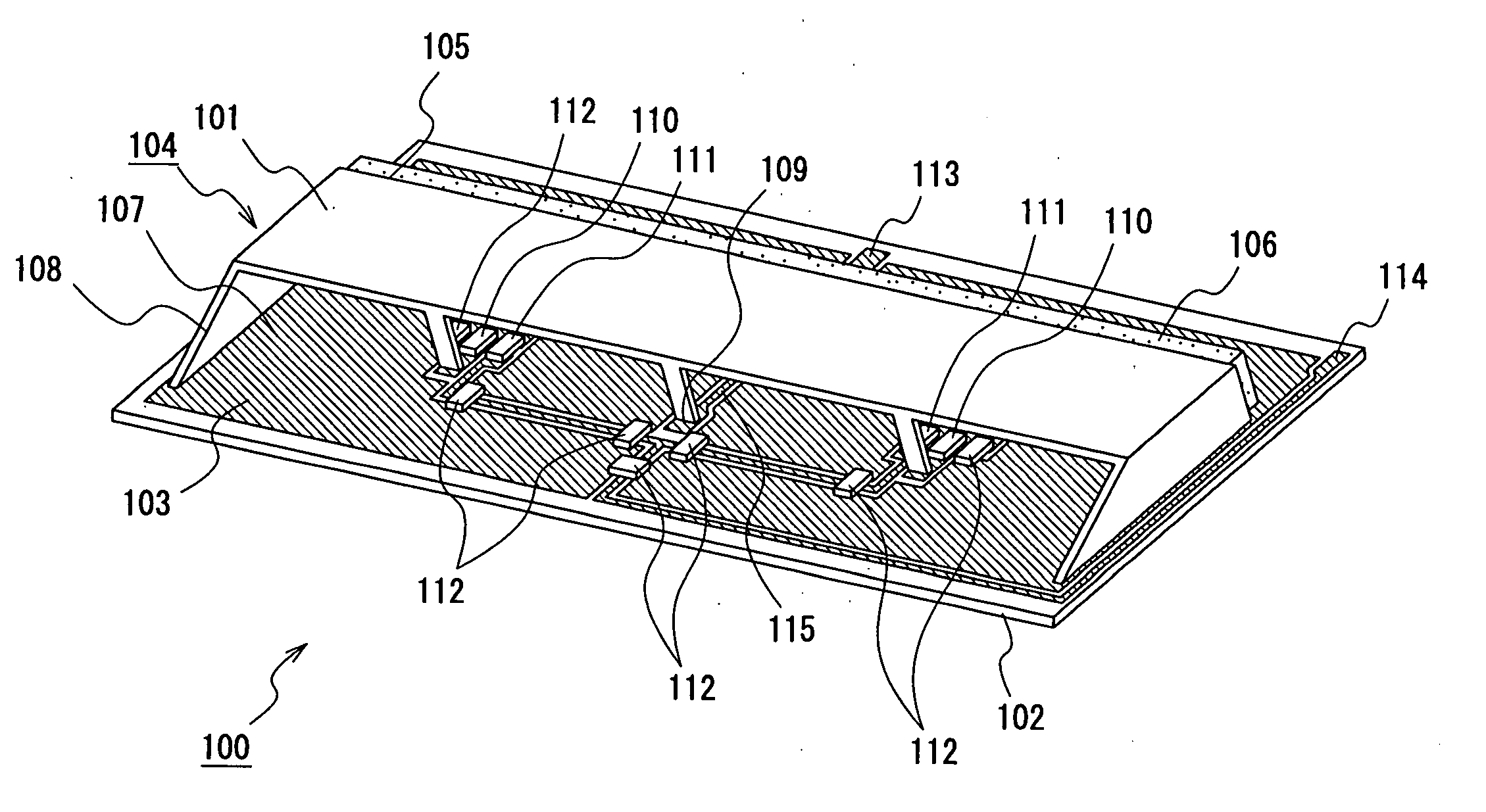
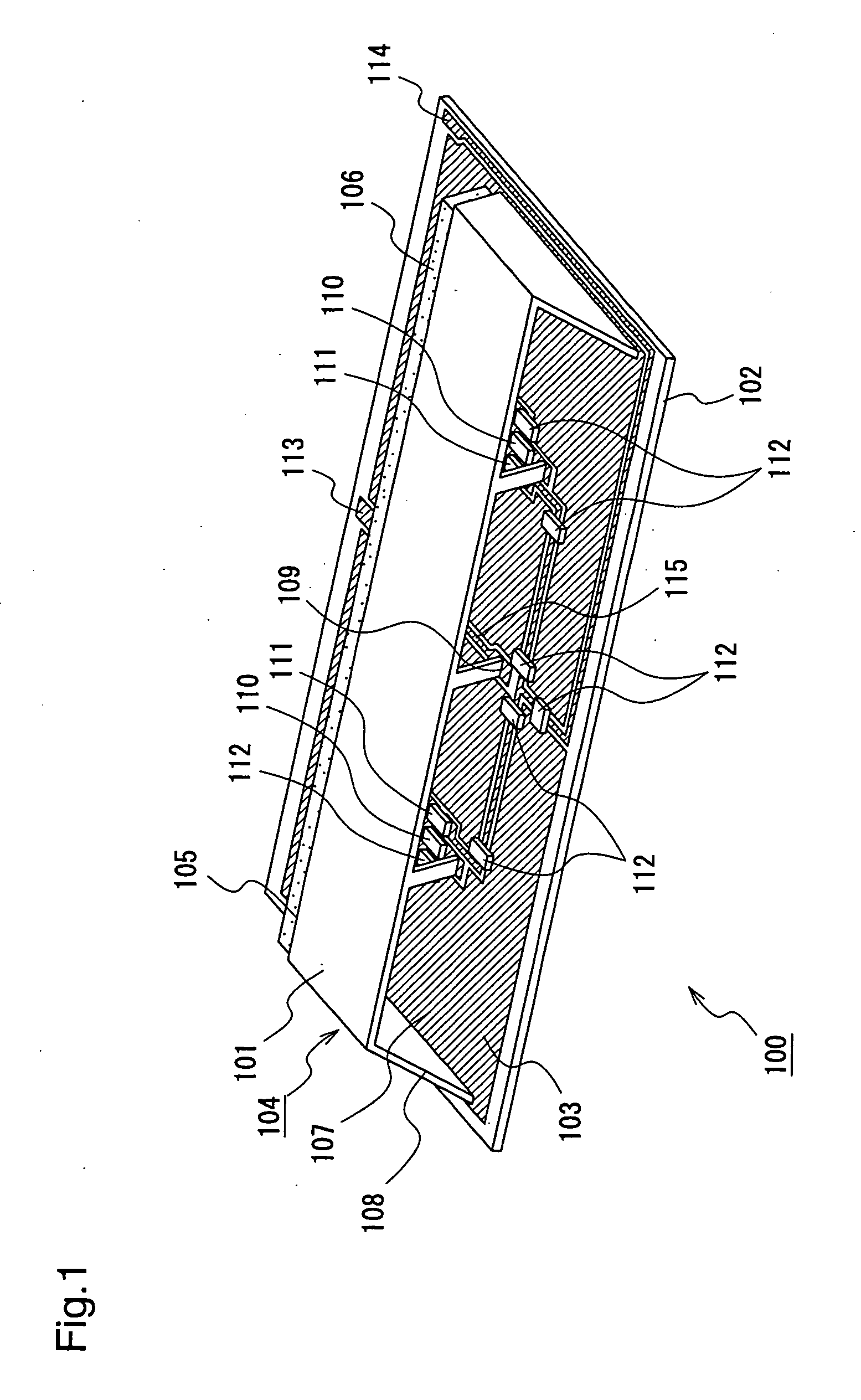
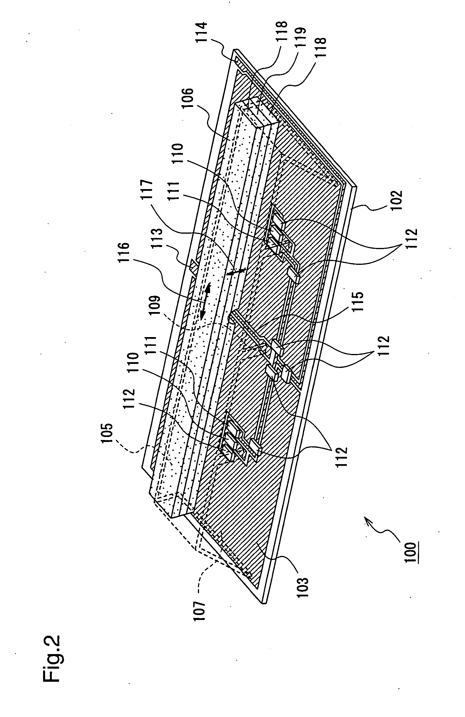
[0041] A digital television broadcast receiving antenna according to a first embodiment will be described with reference to FIGS. 1 to 4.

[0042] Initially, a structure of the digital television broadcast receiving antenna according to the first embodiment will be described with reference to FIGS. 1 and 2.

[0043]FIG. 1 is a diagram illustrating a structure of the digital television broadcast receiving antenna according to the first embodiment, and FIG. 2 is a diagram illustrating the structure of the digital television receiving antenna of FIG. 1 when a metallic plate is eliminated therefrom.

[0044] In FIG. 1, a digital television broadcast receiving antenna 100 includes a waveguide 104 that is formed by a metallic plate 101 and a copper foil 103 on a printed circuit board 102. A main aperture plane 107 is provided at the front of the waveguide 104, and a rear aperture plane 105 is provided at the back of the waveguide 104. A beveling 108 is performed to the main aperture plane 107, ...

embodiment 2

[0070] A digital television broadcast receiver according to a second embodiment of the present invention with reference to FIGS. 6 and 7.

[0071] Initially, a structure of the digital television broadcast receiver according to the second embodiment will be described with reference to FIG. 6. FIG. 6 is a diagram showing the digital television broadcast receiver according to the second embodiment, when viewed from the back.

[0072] In FIG. 6, a digital television broadcast receiver 500 having a stand 509 according to the second embodiment includes a display 501 in a case 510. Here, by exclusively using as the display 501, various types of slim display devices such as a plasma display, a liquid crystal display, an electroluminescence display, or a field emission display, especially a surface-conduction electron-emitter display as an example of the field emission display, the digital television broadcast receiver 500 is realized in a slim shape.

[0073] Further, in the digital television b...


PUM


Abstract

A slim television broadcast receiver employing antennas in which a waveguide is formed by a metallic plate and a copper foil on a printed circuit board, an insulating magnetic element is loaded so as to block one of a pair of aperture planes of the waveguide, the aperture area is enlarged by beveling the other aperture plane, and tuning elements are provided on opposed sides with respect to the center part of the other aperture, which antennas are placed on opposed side ends of the slim television broadcast receiver, thereby performing electronic tuning and phase synthesis diversity reception.

Description

FIELD OF THE INVENTION [0001] The present invention relates to broadcast receiving antennas and television broadcast receivers and, more particularly, to digital television broadcast receiving antennas and digital television broadcast receivers for receiving digital television broadcasts indoors in free locations. BACKGROUND OF THE INVENTION [0002] Conventionally, in analog television broadcasting, in a case of receiving broadcast waves in a weak electric field, reduction in a receiving level by several dB greatly degrades the quality of pictures, or in a case of receiving broadcast waves in an urban area, unpleasant ghost pictures are generated due to waves which are reflected from buildings. Therefore, an antenna which has a high gain in a direction of incoming radio waves and a low gain in a direction of reflected radio waves must be placed in a location where the incoming radio waves are as strong as possible. Thus, as a conventional antenna mount method, there has exclusively b...

Claims


Application Information

Patent Timeline
IPC IPC(8): H01Q13/06H01Q1/22H01Q1/32H01Q5/00H01Q9/04H01Q13/00H01Q13/10H04B1/16
CPCH01Q9/0421H01Q13/06H01Q9/14
Inventor KIRINO, HIDEKININOMIYA, KUNIO
Owner PANASONIC CORP
Why Eureka
Try Eureka