Wrap deformation using subdivision surfaces

a technology of subdivision surfaces and wrapping, applied in the field of computer graphics, can solve the problems of time-consuming and inconvenient, moving a large number of cvs directly, moving a large number of cvs, and requiring a lot of time and effort on the part of users,

Active Publication Date: 2005-08-04
DREAMWORKS ANIMATION LLC
View PDF11 Cites 15 Cited by
  • Summary
  • Abstract
  • Description
  • Claims
  • Application Information

AI Technical Summary

Benefits of technology

[0015] The present invention overcomes the limitations of the prior art by using a subdivision surface as a binding domain to wrap deform a model. A subdivision surface is derived from a wrap that has been associated with a model. The subdivision surface is bound to the model by associating points on the subdivision surface with control vertices of the model. In response to a change in the position of a control vertex of the wrap, the subdivision surface is redetermined, and the updated surface locations are used to redetermine the position of the model's control vertices, thereby deforming the model.

Problems solved by technology

Creating a model requires a lot of time and effort on the part of a user.
In order to deform a model to a particular shape, a user often must move a large number of CVs, due to the natural constraints of parametric surfaces.
Moving large numbers of CVs directly, one by one, is time-consuming and not very intuitive.
The problem with this type of wrap deformer is that it doesn't scale well with the size of the model.
Large models at high resolution may require a huge number of cells, and the evaluation and update process of the deformer is very slow and consumes a lot of memory.
Conversely, using a smaller number of cells will introduce discretization artifacts in the model during deformation.
This approach is faster than the space cell division approach mentioned above; however, it suffers from many problems and artifacts due to the simplistic nature of the linear interpolation scheme.
Creating each image by manually editing each CV of the model is nearly impossible.
Not only does it require a great deal of work, it also does not result in a convincing performance for the animated model because of the awkwardness of the interface.
One disadvantage is that deformations of the wrap result in excessive linear interpolation artifacts in the model.
The changes made to the wrap are often discontinuous due to the wrap's lack of resolution, and these discontinuities end up getting transferred to the model.
These artifacts are most noticeable when there is a significant difference between the resolution of the wrap and the resolution of the model.
The artifacts indicate problems with the cell splitting of the polygonal mesh wrap and problems with the weighted contributions of the wrap on the control vertices of the model.
Another disadvantage of prior art software is that it is slow.
The slowness is severe enough to make wrap deformation inadequate for character setup purposes.
For example, it cannot be used for sculpting new blendshapes from existing models, unless the models are very small and not detailed.
When existing software is used to wrap deform a detailed, realistic model, it runs so slowly that it is virtually unusable for modeling and animation.

Method used


Image

  • Wrap deformation using subdivision surfaces
  • Wrap deformation using subdivision surfaces
  • Wrap deformation using subdivision surfaces

Examples


Embodiment Construction

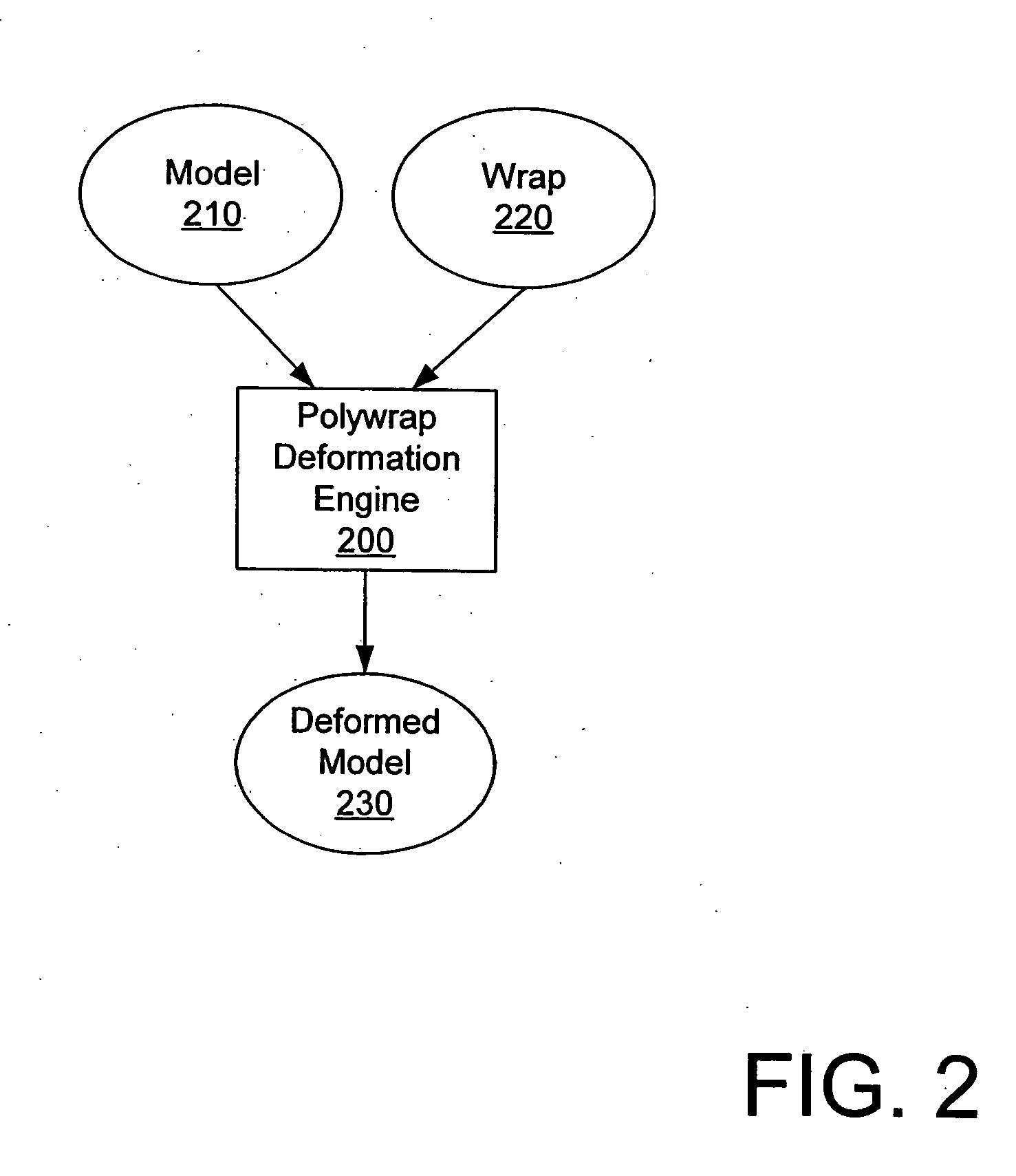
[0036]FIG. 2 illustrates a block diagram overview of the use of one embodiment of a software component for wrap deforming a model. FIG. 2 includes a polywrap deformation engine 200, a model 210, a wrap 220, and a deformed model 230. Polywrap deformation engine 200 is a software component used to wrap deform a model 210. The inputs of the deformation engine 200 are a model 210 and a wrap 220. The output of the deformation engine 200 is a deformed model 230. After a user is satisfied with the deformed model 230, the deformed model 230 is further processed in order to add special effects such as lighting and shadows. For example, the deformed model 230 may be input into a rendering engine (not shown).

[0037] One of the inputs to polywrap deformation engine 200 is a model 210. The model 210 is the figure that will be deformed. The model 210 may be built using a variety of methods known to those skilled in the art, such as scanning in a three-dimensional sculpture or creating a model fro...


PUM


Abstract

Deformations are applied to a model using a subdivision surface. Given a wrap and model, a subdivision surface is calculated from the wrap. The model is then bound to the subdivision surface. When the wrap is deformed, the subdivision surface is recalculated. The model is then deformed based on changes in the subdivision surface. Binding parameters may be assigned to control vertices in the wrap to control the application of the deformation to the surface.

Description

BACKGROUND OF THE INVENTION [0001] 1. Field of the Invention [0002] This invention relates generally to computer graphics and, more specifically, to wrap deforming a model using subdivision surfaces. [0003] 2. Background Art [0004] Computers are widely used to model figures, from insects and monsters to human beings. The basic view of a figure is known as a model. Creating a model requires a lot of time and effort on the part of a user. In general, a user creates a model by scanning in a three-dimensional sculpture or by creating a model by hand based on a traditional two-dimensional drawing. Frequently, a computer-generated (CG) model is represented mathematically by one or more parametric surfaces. A CG model usually comprises a large number of parametric surfaces connected together. A parametric surface is a description of a two-dimensional object in three-dimensional space where every point on the parametric surface can be mapped to a pair of parameters (u, v). Many types of par...

Claims


Application Information

Patent Timeline
Patent Type & Authority Applications(United States)
IPC IPC(8): G06T17/20G06T17/40
CPCG06T19/00G06T17/20G06T19/20G06T2219/2021A47J36/2488A47J37/041A47J37/0745A47J37/0786
Inventor SEPULVEDA, MIGUEL A.
Owner DREAMWORKS ANIMATION LLC
Why Eureka
Try Eureka