Projector

a projector and projector technology, applied in the field of projectors, can solve the problems of inability to adjust the illumination light amount at high speed, the operation is not easy to control, and the adjusting device for the illumination light amount is large, so as to achieve the effect of reducing the burden of image processing and high contrast and image quality

Inactive Publication Date: 2005-08-04
SEIKO EPSON CORP
View PDF2 Cites 17 Cited by
  • Summary
  • Abstract
  • Description
  • Claims
  • Application Information

AI Technical Summary

Benefits of technology

[0009] Therefore, an aspect of the invention can provide a projector capable of easily achieving a contrast ratio higher than the contrast ratio resulting from the nature of the liquid-crystal light valve alone, by use of a simple mechanism.
[0011] In the above projector, because the auxiliary light modulating device attenuates the light intensity of image light formed by the main light modulating device by modulation, light intensity can be adjusted cumulatively by the main and auxiliary light modulating devices. In this case, the main and auxiliary light modulating devices are operated harmoniously by the signal processing circuit, making it possible to project image light at a contrast ratio exceeding by far the contrast ratio that can be realized by the main light modulating device singly.
[0012] In an example of the invention, in the projector, the illuminating device generates different three colors of illumination light, the main light modulating device having three color-light modulating devices illuminated respectively by the three colors of illumination light and separately modulating the respective colors of illumination light, and a light-combining member for combining together image light of the respective colors from the three color-light modulating devices. In this case, the three colors of illumination light can be modulated separately and combined together, thus making possible to project a color image high in brightness.
[0013] In an example form of the invention, in the projector, the auxiliary light modulating device can be arranged between the light combining member and the projection optical system. In this case, the auxiliary light modulating device for attenuation is not provided for the color-light modulating device for each color but the light intensity of image light that has passed through the main light modulating device is attenuated by a single auxiliary light modulating device, such as a single liquid-crystal light valve, thus making the auxiliary light modulating device or the projector cheap in price.
[0016] In another example of the invention, the signal processing circuit can determine the drive signal to be sent to the auxiliary light modulating device by referring to the maximum value of the signals of respective colors in the inputted image signal. In this case, the main light modulating device can express the intensity level of each color accurately while the auxiliary light modulating device can achieve a desired light reduction, making possible to project an image high in contrast and image quality.
[0017] In another example of the invention, the signal processing circuit can use signals of respective colors in the inputted image signal as they are as the drive signals to the main light modulating device, and the drive signal to the auxiliary light modulating device is determined by making a predetermined operation on the signals of respective colors in the inputted image signal. In this case, a desired contrast can be achieved by processing the image signals of respective colors. Besides, operation processing is satisfactorily performed on the auxiliary light modulating device only. Thus, the burden of image processing is lessened.

Problems solved by technology

However, with a related art projector in which the illumination light amount adjusting device is arranged between the light source and the liquid-crystal light valve, the illumination light amount adjusting device tends to be large sized because of the mechanical mechanism etc. used, and operation is not easy to control.
Particularly, illumination light amount cannot be adjusted at high speed because of response time limitation of the mechanical mechanism, and the like.
Furthermore, because illumination light amount cannot be adjusted minutely on a pixel unit basis, it is impossible to increase the contrast ratio, the light-intensity difference within one projection surface.

Method used


Image

  • Projector
  • Projector
  • Projector

Examples


Embodiment Construction

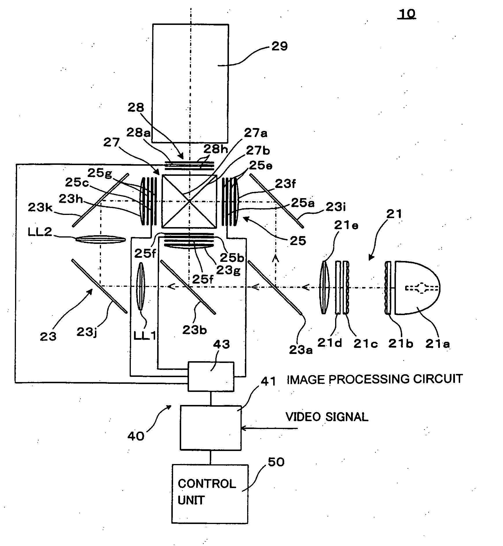
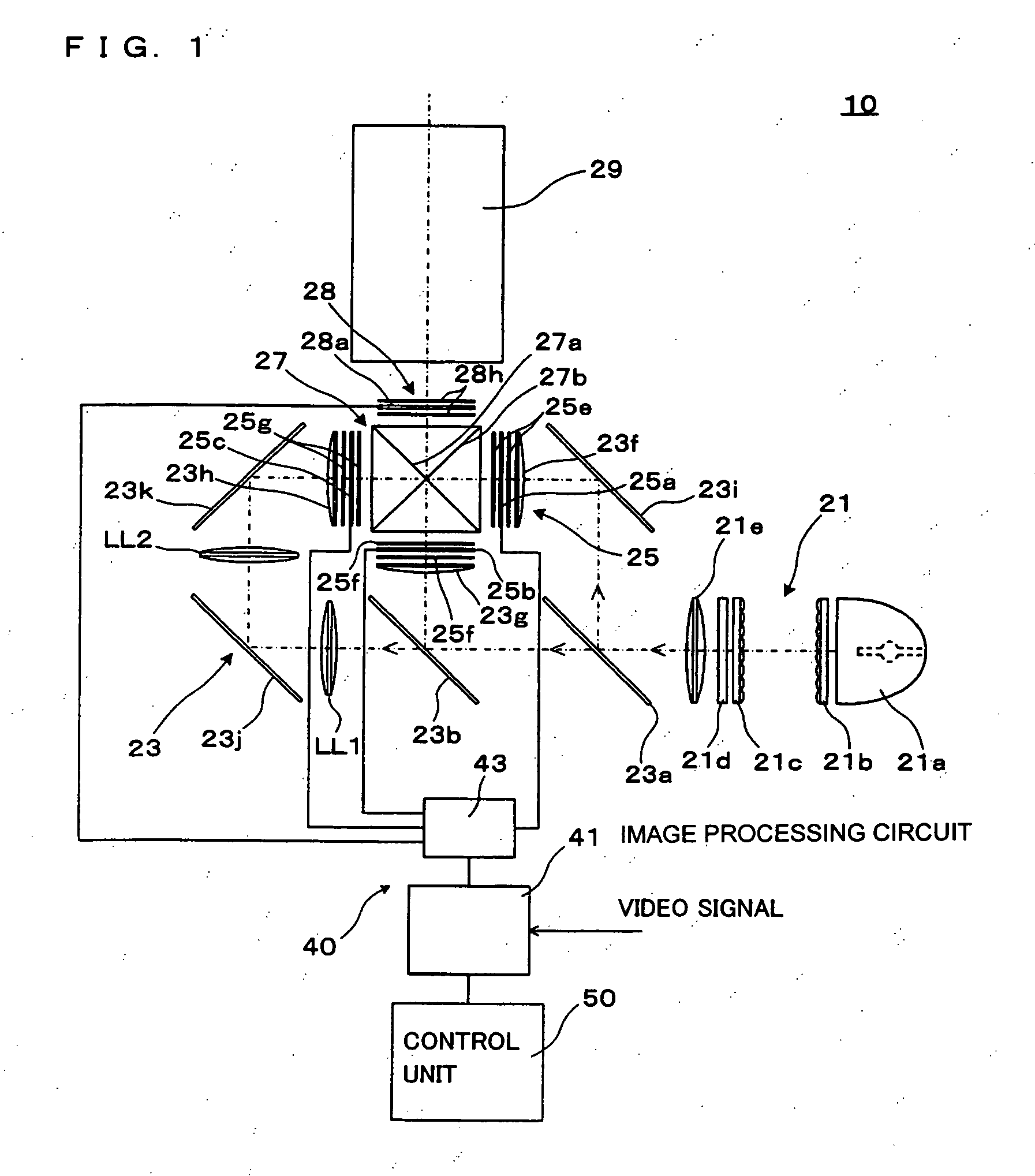
[0023]FIG. 1 is an exemplary view explaining the construction of a projector according to an embodiment of the invention. The projector 10 can include a light source 21 for generating source light, a light-splitting system 23 for splitting the source light from the light source 21 into three colors of RGB, a main light modulator 25 illuminated by the respective colors of light exiting from the light-splitting system 23, a light-combining optical system 27 for combining the respective colors of image light from the main light modulator 25, an auxiliary light modulator 28 which is arranged on the light-exit side of the light-combining optical system 27 and which carries out two-dimensional light intensity modulation on the image light, and a projection lens 29 for projecting the image light passed the auxiliary light modulator 28 to a projection surface. Furthermore, the projector 10 can include a signal-processing circuit 40 for operating the light modulators for respective colors, e...


PUM

PropertyMeasurementUnit
light intensityaaaaaaaaaa
colorsaaaaaaaaaa
structureaaaaaaaaaa

Abstract

Aspects of the invention provide a projector capable of comparatively easily achieving a contrast ratio higher than the original contrast ratio of the liquid-crystal light valve by a simple mechanism. The illumination light modulated by liquid-crystal light valves, i.e., image light, can be combined together in a cross dichroic prism, and then light intensity of suitable pixels is reduced by a proper amount by a liquid-crystal light valve, and then sent to a projection lens. The image light entering the projection lens can be projected to a projection surface. Because the light intensity of the image light formed by the liquid-crystal light valves is appropriately attenuated at suitable pixel areas by the liquid-crystal light valve, image light projection with a contrast ratio exceeding by far the contrast ratio achievable by the liquid-crystal light valves alone is possible due to cumulative light-intensity adjustment.

Description

BACKGROUND OF THE INVENTION [0001] 1. Technical Field of Invention [0002] Aspects of the invention relate to a projector for projecting an image by use of a liquid-crystal light valve and other light modulating devices. [0003] 2. Description of Related Art [0004] Some related art projectors form a color image by combining, through a special prism, images of respective colors separately formed by sending three colors, RGB, of illumination light to three liquid-crystal light valves, for example. See, for example, JP-A-2002-365720. The contrast ratio achievable on such related art projector, at present, has the upper limit of approximately 1000:1. [0005] Meanwhile, on the CRT or a film, a contrast ratio of 3000:1 or higher is obtained, depending on the viewing environment. Incidentally, according to movie directors and movie critics, where contrast ratio is concerned the ultimate target images desired for movies, require a 5000:1 ratio. Taking account of film overshoot (peaks), nearly ...

Claims


Application Information

Patent Timeline
Patent Type & Authority Applications(United States)
IPC IPC(8): G02F1/13G02B27/18G02F1/1335G02F1/1347G03B21/00G03B21/14G09G3/20G09G3/34G09G3/36H04N5/74H04N9/31
CPCH04N9/3197H04N9/3105
Inventor SUZUKI, MASAYUKIKOBAYASHI, MAMORU
Owner SEIKO EPSON CORP
Why Eureka
Try Eureka