Anamorphic converter, lens device using the same, and image-taking device using the same

an anamorphic converter and lens device technology, applied in the field of anamorphic converters, can solve the problems of complicated mechanism and achieve the effect of excellent optical performance and small siz

Inactive Publication Date: 2005-08-04
CANON KK
View PDF5 Cites 16 Cited by
  • Summary
  • Abstract
  • Description
  • Claims
  • Application Information

AI Technical Summary

Benefits of technology

[0010] The present invention is directed to an anamorphic converter suitable for digital cinematography, small in size and having excellent optical performance.
[0013] According to the present invention, an anamorphic converter can be realized which is suitable for digital cinematography, and small in size and having excellent optical performance.

Problems solved by technology

However, correcting means within the converter must be driven synchronously with the focusing of the image-formation optical system, thereby necessitating a complicated mechanism.

Method used


Image

  • Anamorphic converter, lens device using the same, and image-taking device using the same
  • Anamorphic converter, lens device using the same, and image-taking device using the same
  • Anamorphic converter, lens device using the same, and image-taking device using the same

Examples


first embodiment

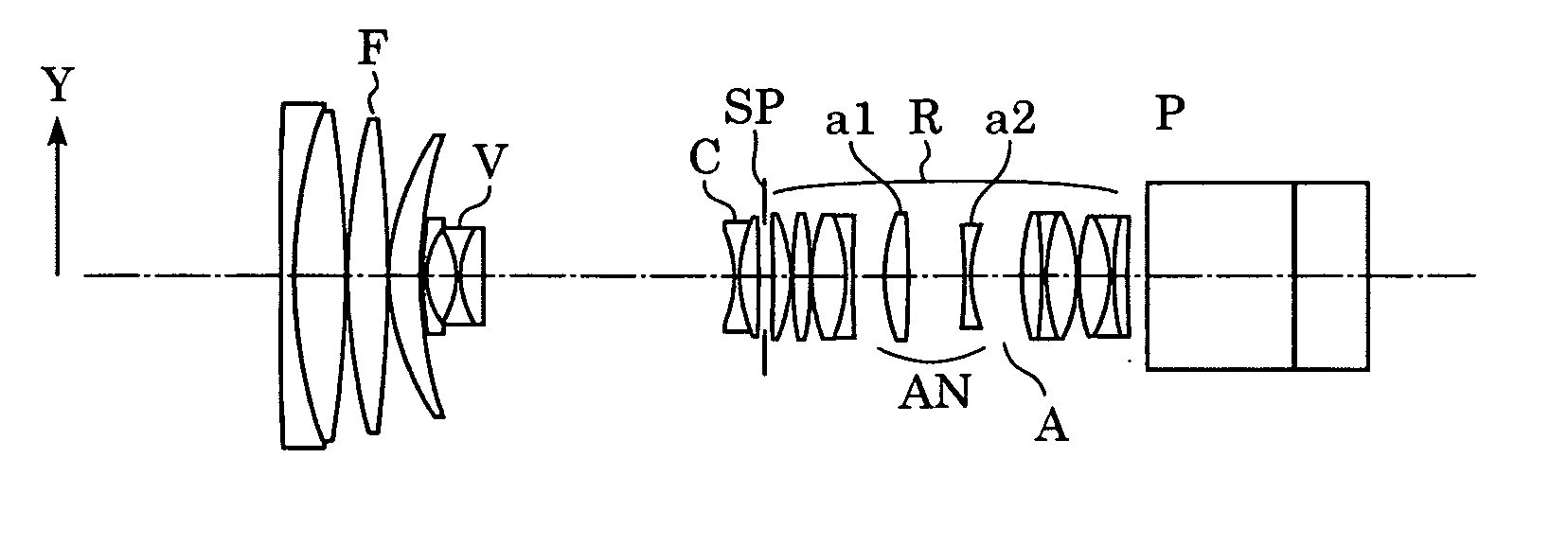
[0075] Now, embodiments of the present invention will be described. The configuration of a first embodiment of the present invention wherein an arrangement including an anamorphic converter disposed at the image side of the image-formation optical system is applied, will be described now.

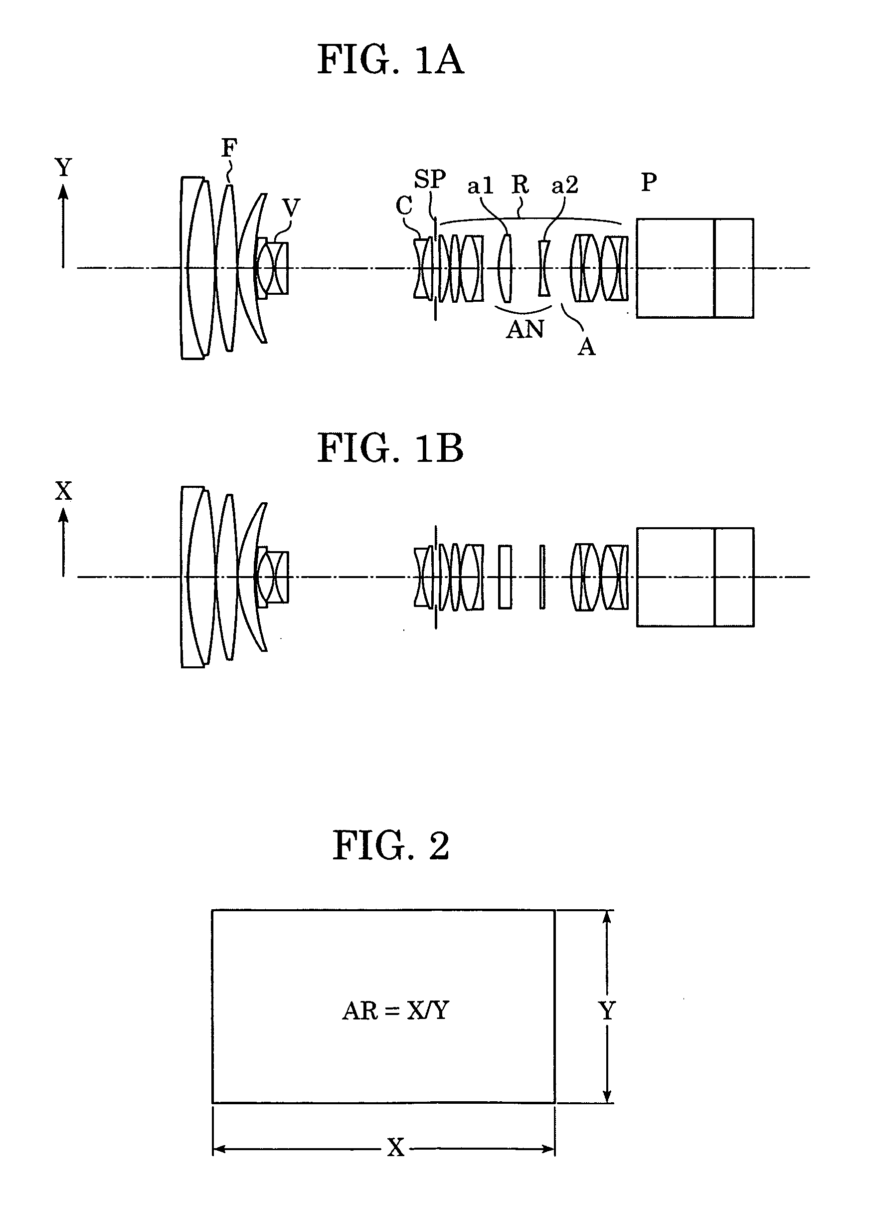
[0076]FIGS. 1A and 1B are diagrams illustrating the configuration of the first embodiment of the present invention. FIG. 1A is a cross-sectional diagram illustrating the lens configuration in the Y direction with an anamorphic converter inserted, and FIG. 1B is a cross-sectional diagram illustrating the lens configuration in the X direction with the anamorphic converter inserted. FIG. 13 is a diagram of longitudinal aberration in the X direction, in a numerical example according to the first embodiment wherein fx=10.3 mm, fy=13.6 mm, and object distance is 2.5 m. FIG. 14 is a diagram of longitudinal aberration in the Y direction, in a numerical example according to the first embodiment wherein fx=1...

second embodiment

[0084] Now, the configuration of a second embodiment of the present invention wherein an arrangement including an anamorphic converter disposed at the object side of the image-formation optical system is applied, will be described.

[0085]FIGS. 23A and 23B are diagrams illustrating the configuration of a second embodiment of the present invention. FIG. 23A is a cross-sectional diagram illustrating the lens configuration in the X direction with an anamorphic converter inserted, and FIG. 23B is a cross-sectional diagram illustrating the lens configuration in the Y direction with the anamorphic converter inserted. FIG. 24 is a diagram of longitudinal aberration in the X direction at the wide angle end in a numerical example according to the second embodiment, wherein object distance is at infinity. FIG. 25 is a diagram of longitudinal aberration in the Y direction at the wide angle end in a numerical example according to the second embodiment, wherein object distance is at infinity. FIG...


PUM


Abstract

An anamorphic converter, which can be inserted into and removed from a lens group of an image-formation optical system, includes an anamorphic lens that satisfies the following conditions 0.9<(AR1·βx) / (AR2·βy)<1.1 (AR22+1)·βy2 / (AR12+1)>1 wherein βx represents a first focal distance magnification scale at a first cross-section containing an optical axis of the anamorphic lens, βy represents a second focal distance magnification scale at a second cross-section which is perpendicular to the first cross-section and contains the optical axis, AR1 represents an aspect ratio of an image-taking range in a field of the image-formation optical system, and AR2 represents an aspect ratio at an effective range of an image-taking unit disposed at an object image side of the lens group. As such, there is provided an anamorphic converter which is small and has high optical performance, suitable for digital cinematography.

Description

BACKGROUND OF THE INVENTION [0001] 1. Field of the Invention [0002] The present invention relates to an anamorphic converter used with image-taking devices such as film cameras, television cameras, video cameras, or the like, for taking pictures with an aspect ratio which differs from that of the imaging device. [0003] 2. Description of the Related Art [0004] Various techniques for recording and playback of images with conversion of aspect ratio have been conventionally proposed. Particularly, in the field of cinematography, a technique is widely used with a CinemaScope format (aspect ratio 2.35:1) picture recording / playback system wherein the picture is optically horizontally compressed using an anamorphic lens so as to be taken on film, and also shown at the time of playback by optically horizontally expanding the image on film using an anamorphic lens. [0005] Known anamorphic converters include front converters which are attached to the object side of an image-formation optical s...

Claims


Application Information

Patent Timeline
Patent Type & Authority Applications(United States)
IPC IPC(8): G02B7/10G02B9/10G02B13/08G02B13/18G02B27/09
CPCG02B13/08
Inventor NURISHI, RYUJIYOSHIMI, TAKAHIRO
Owner CANON KK
Why Eureka
Try Eureka