Condition monitor for an electrical distribution device

Active Publication Date: 2005-08-04
HITACHI ENERGY SWITZERLAND AG
View PDF8 Cites 65 Cited by
  • Summary
  • Abstract
  • Description
  • Claims
  • Application Information

AI Technical Summary

Benefits of technology

[0013] The principle advantage of the present invention is the timely identification and signaling of a fault under operations or a possible fault condition of an electrically operated distribution devices and switchgear with moving parts, such as a circuit breaker.
[0014] The utility or power grid owner wants to increase the availability and reduce the service of equipment. For example to avoid a failure and a loss of transmitted energy, time based maintenance may be carried out on a circuit breaker. However time based maintenance might result in unnecessary repair of the circuit breaker. Unnecessary repair causes a higher risk of fault at installation and service. It may also increase the service costs, as for example the time to find the fault and repair it, which will affect the total cost of the outage. A unit for a circuit breaker or other device with moving parts which can indicate and show the different incurrent faults will provide timely information about need for maintenance actions and reduce power failures and reduce the cost of power outage.
[0015] The electrical drive of a distribution device with a moving part, such as a circuit breaker, gives previously undreamed of possibilities to carry out condition monitoring and so supervise and analyse t

Problems solved by technology

Moving parts of equipment installed outdoors are subject to many factors that can cause wear, damage or failure, factors including weather conditions, corrosion, lightning strike, animal intrusions etc.
However, the costs to the utility owner of preventive maintenance and of scheduled maintenance are high.
On the other hand, when a circuit breaker fails the costs or penalties arising from an otherwise avoidable temporary blackout, brownout or other power interruption may be extremely high when a large number of in

Method used


Image

  • Condition monitor for an electrical distribution device
  • Condition monitor for an electrical distribution device
  • Condition monitor for an electrical distribution device

Examples


Embodiment Construction

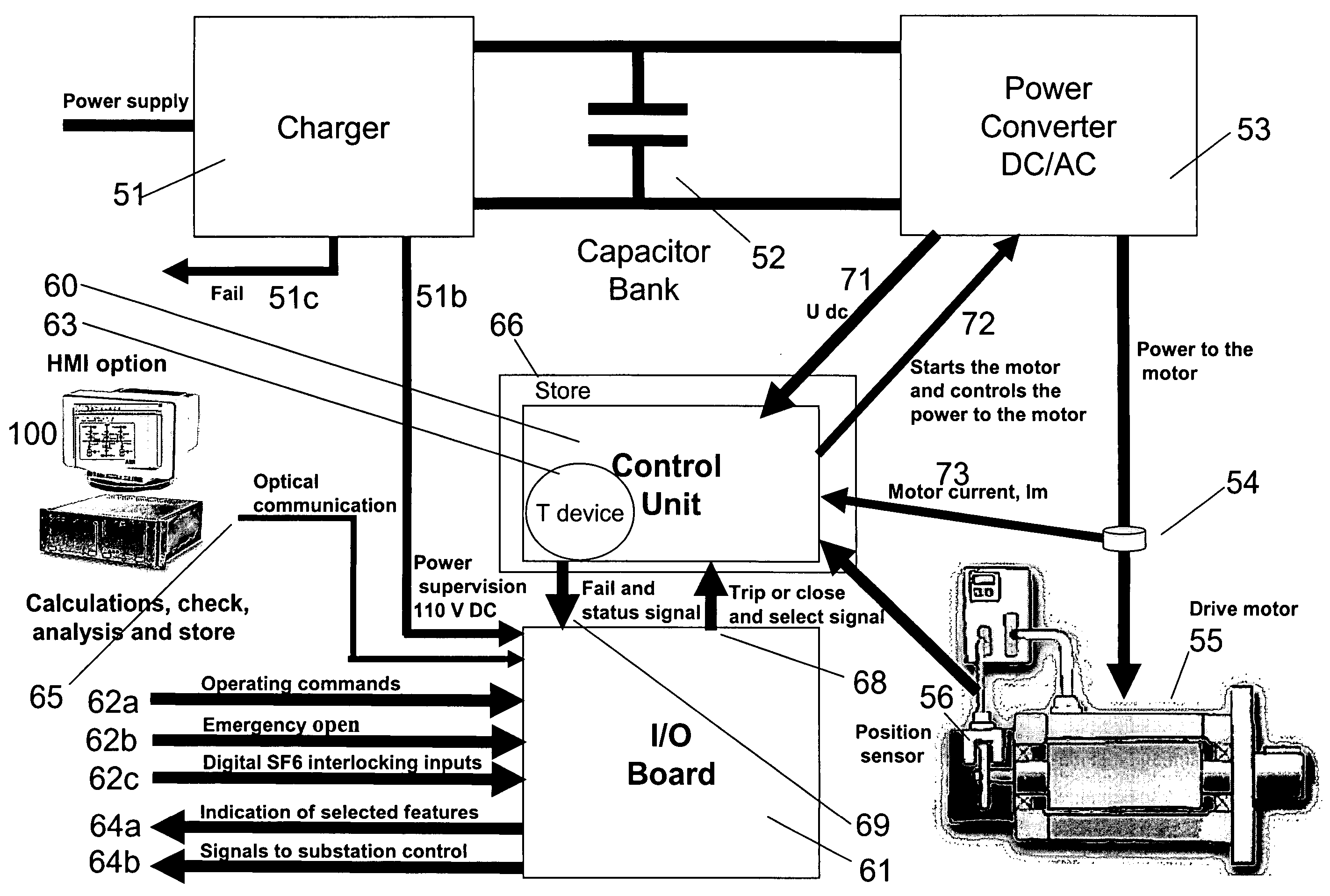
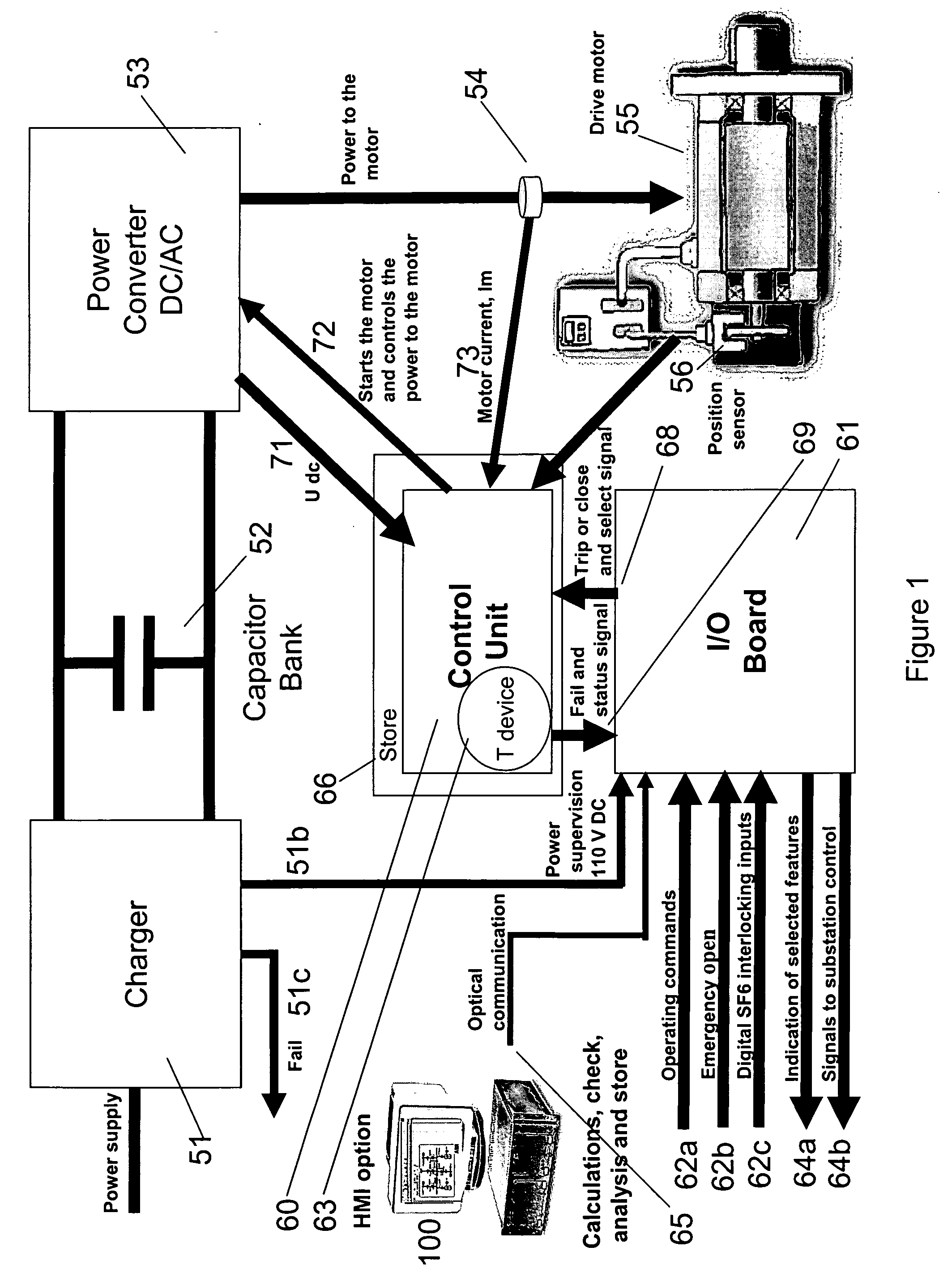
[0027] The condition monitor for an electrically actuated device in an electrical distribution system according to an embodiment of the present invention concerns devices with one or more moving parts that are operated by electrically powered drive means or electrically powered actuator means. Such distribution switchgear and devices with a moving part that is operated by an electrically powered actuator may include for example: a circuit breaker, a disconnector, a switch disconnector, an earthing switch; a switchgear insulator with integrated electric operating device; protection device, overload protection device.

[0028] A condition monitor for an electrically actuated circuit breaker is described here in detail as an exemplary practice of an embodiment of the present invention.

[0029] The condition monitor for a circuit breaker according to an embodiment of the present invention concerns circuit breakers that are operated by electrical drive means or actuator means. The electrica...


PUM


Abstract

The invention is a condition monitor for a switchgear device in an electrical power distribution system. The switchgear device is arranged with an electrically powered actuator for operating a moveable part of the switchgear device, for example, operating the opening and/or closing of a circuit breaker. The switchgear device has a control unit with means to receive state information from the actuator, and panel means to present information via an HMI. The HMI may be accessed remotely. In other aspects of the invention a method, a human-machine interface and a computer program for carrying out the method are described.

Description

TECHNICAL FIELD [0001] The present invention is concerned with a condition monitor for equipment in an electrical power distribution system. In particular it is concerned with a condition monitor for electrical distribution devices including an electrical actuator, a device such as a circuit breaker, and comprises an improved human-machine interface (HMI) for condition monitoring and control purposes. BACKGROUND ART [0002] Electrical power distribution systems for industrial and residential power users a range of equipment that incorporate one or more moving parts, the majority of which equipment is installed outdoors. Such equipment include for example circuit breakers, earthing switches, overload protectors. A circuit breakers is an example of a distribution device with one or more moving parts. Circuit breakers of different types are used to control and adjust the distribution power, switching power feeds on and off and switching from or to different lines or feeders as required....

Claims


Application Information

Patent Timeline
IPC IPC(8): H01H11/00
CPCH01H11/0062H01H2071/006H01H2003/266H01H33/36
Inventor NILMAN-JOHANSSON, KRISTINAWALLIN, KENNETHSCHREURS, EMILE
Owner HITACHI ENERGY SWITZERLAND AG
Why Eureka
Try Eureka