Mobile terminal and radio access point in radio access system

Inactive Publication Date: 2005-08-04
FUJITSU LTD
View PDF4 Cites 33 Cited by
  • Summary
  • Abstract
  • Description
  • Claims
  • Application Information

AI Technical Summary

Benefits of technology

[0034] An object of the present invention is to provide a technique for improving the throughout of a

Problems solved by technology

In such a radio access system, burst errors often occur on a radio transmission path due to fading, etc., resulting in data packet loss.
This can, for example, lead to a situation where the TCP performs flow control between the mobile terminal and the host when the RLP is in the process of data packet retransmission between the mobile terminal and the radio access point in order to recover the lost data and, hence, to the problem that data throughput greatly decreases.
Another factor that reduces the data throughout is the inability to secure bandwidth for a new data transmission because of the occurrence of unnecessary retransmission.
Here, unnecessary retransmission occurs, for example, when the retransmissi

Method used


Image

  • Mobile terminal and radio access point in radio access system
  • Mobile terminal and radio access point in radio access system
  • Mobile terminal and radio access point in radio access system

Examples


first embodiment

[0057]FIG. 8 shows a first configuration example of the mobile terminal 10 according to the present invention.

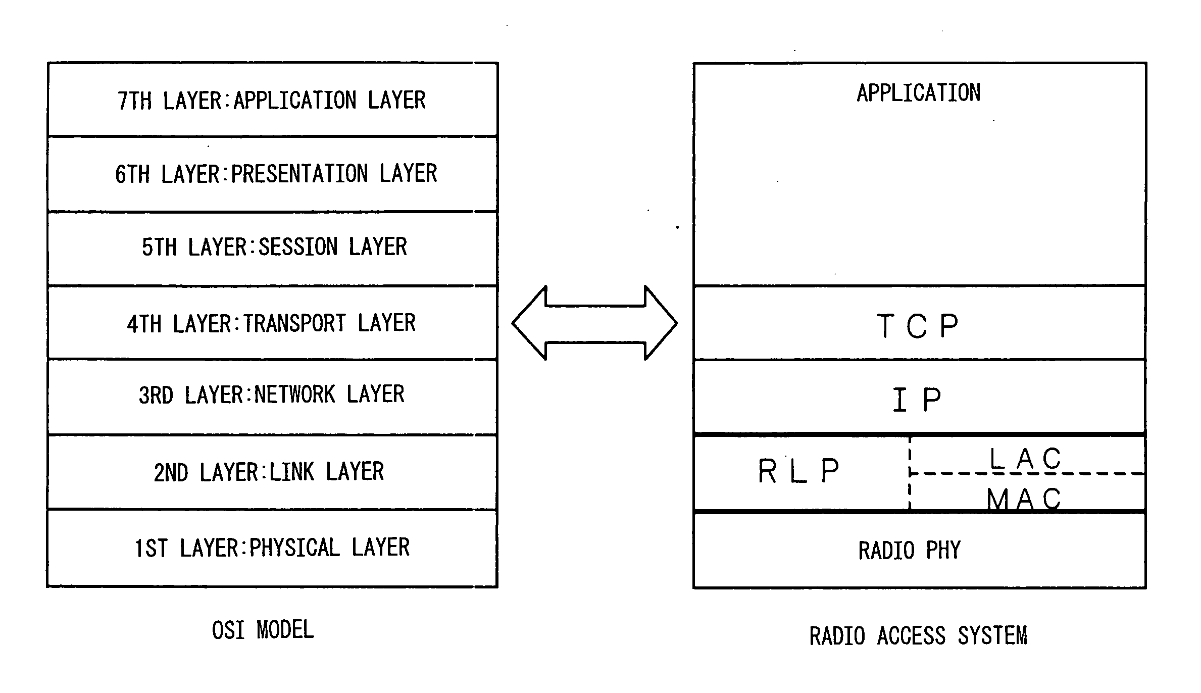
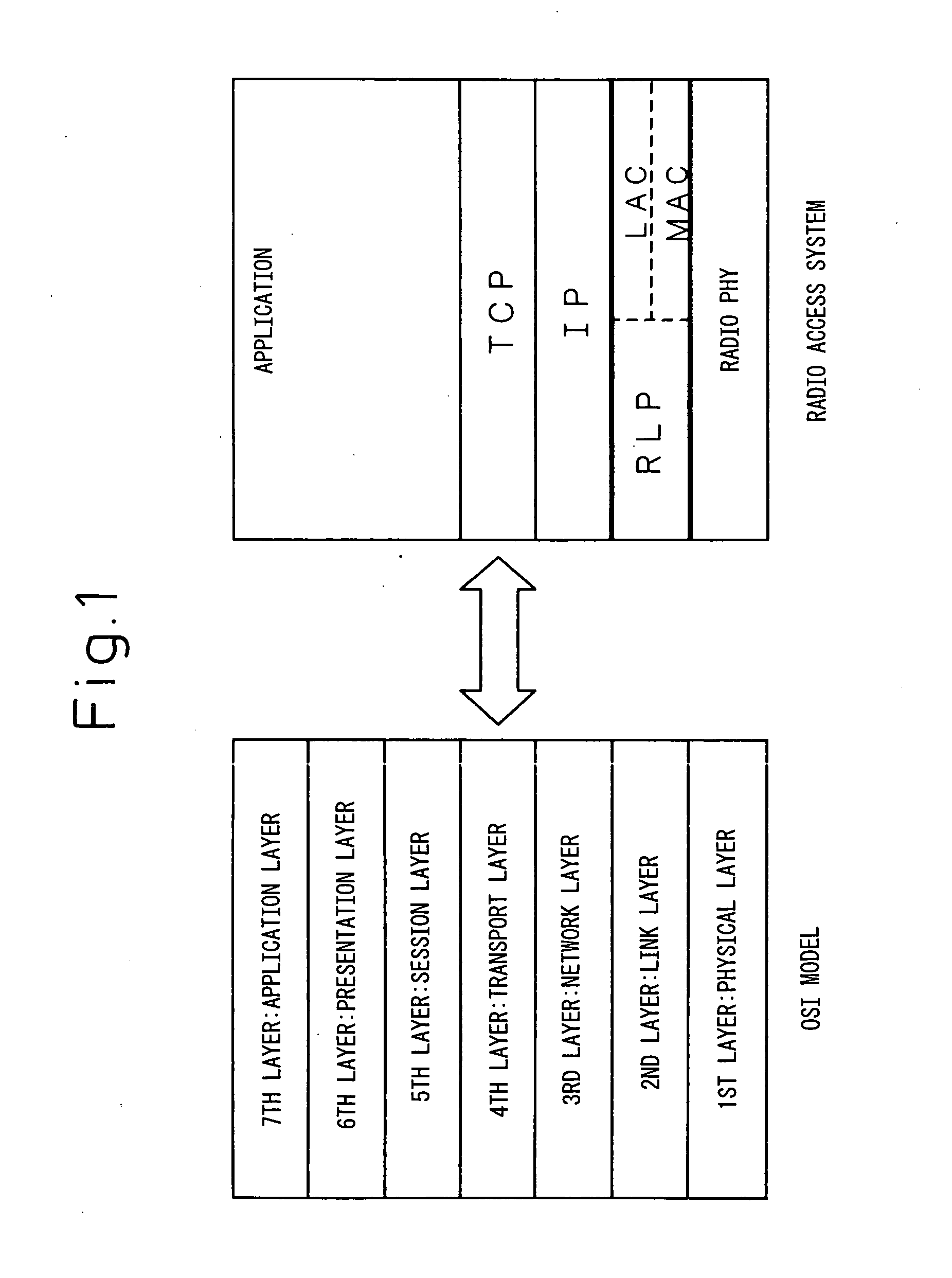
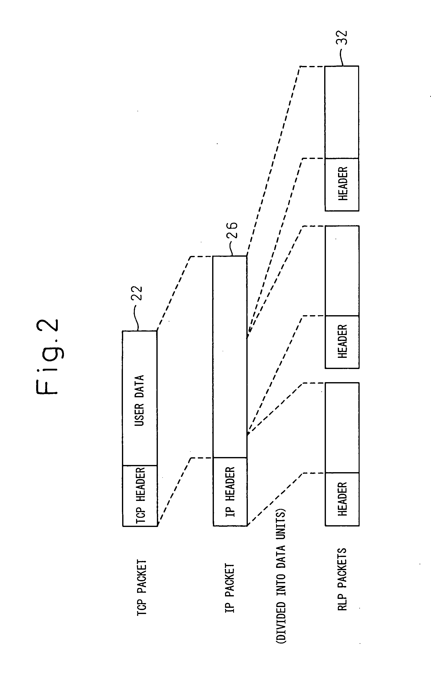
[0058] In FIG. 8, a TCP frame processing section 20 accepts transmit data (user data) and creates the TCP packet 22 shown in FIG. 2; it also extracts received data from the TCP packet passed from an IP frame processing section 24. The IP frame processing section 24 receives the TCP packet 22 from the TCP frame processing section 20 and creates the IP packet 26 shown in FIG. 2; it also extracts the TCP packet 22 from the IP packet 26 passed from an RLP packet combining section 34, and passes the TCP packet 22 to the TCP frame processing section 20. An RLP frame processing section 28 and an RLP packet fragmenting section 30 create the RLP packets 32 from the IP packet 26, as shown in FIG. 2. An RLP packet extracting section 32 extracts parameters concerned with the radio link, such as the number of retransmissions per unit time, the packet error rate, and the retransmission pr...

second embodiment

[0061]FIG. 13 is a diagram showing the flow of QoS information on the configuration diagram of FIG. 6 according to the present invention. As shown by dashed lines in FIG. 13, the header of the TCP packet transferred from the host 16 or the header of the IP packet transferred from the mobile IP router 14 is extracted at the radio access point 12, and the quality information contained in the header is reflected in the retransmission control at the RLP layer.

[0062]FIG. 14 shows a first configuration example of the radio access point according to the second embodiment of the present invention. In an IP frame processing section 50 newly provided in the radio access point, an IP header detecting section 52 extracts the IP header from the IP packet received from the bridge 18 (FIG. 13), and a traffic class field extracting section 54 extracts the information stored in the traffic class field 40 (FIG. 4) of the IP header. A table searching / QoS parameter generating section 56 determines the ...


PUM


Abstract

A mobile terminal (10) in a radio access system detects communication quality such as frequency of retransmission, packet error rate, etc. on an RLP-based radio link, and converts the communication quality into a traffic class in IP or a window size in TCP. Based on the thus converted communication quality, flow control is performed at IP or TCP. At a radio access point (12) also, quality information is extracted from an IP header or a TCP header, and the number of packets into which the IP or TCP packet is to be fragmented, retransmission count, etc. are set based on the extracted information.

Description

CROSS REFERENCE TO RELATED APPLICATIONS [0001] This is a continuation of International Application PCT / JP03 / 04365, published in Japanese, with an international filing date of Apr. 4, 2003.TECHNICAL FIELD [0002] The present invention relates to a mobile terminal and a radio access point in a radio access system in which the terminal is connected to the access point via a radio link. BACKGROUND ART [0003]FIG. 1 shows the architecture of a radio access system for comparison with the OSI model. [0004] In FIG. 1, the first layer (physical layer) of the OSI model, in the radio access system, provides for processing such as encoding and modulation in a radio transmission path. The second layer (data link layer), in the radio access system, provides for the detection of errors on the radio transmission path and mechanisms to cope with transmission delays or data losses or to ensure data bandwidth, in order to alleviate the effects of a failure that may occur in the radio transmission path. ...

Claims


Application Information

Patent Timeline
IPC IPC(8): H04L12/56H04L29/06H04L29/08H04W24/00H04W28/04H04W28/06H04W28/10H04W80/00H04W80/06
CPCH04W24/00H04W28/04H04W28/06H04W28/10H04W80/00H04L69/32H04L69/16H04L69/166H04L69/163H04L69/168H04W80/06H04L69/325H04L69/326
Inventor MORI, MASARU
Owner FUJITSU LTD
Why Eureka
Try Eureka