
Temperature compensated optical multiplexer

a technology of optical multiplexers and temperature compensation, applied in the direction of optics, optical waveguide light guides, instruments, etc., can solve the problems of adversely affecting operation, change in optical path length, and difficulty in precise temperature control

Inactive Publication Date: 2005-08-04
TEXAS TECH UNIVERSITY
View PDF9 Cites 16 Cited by
  • Summary
  • Abstract
  • Description
  • Claims
  • Application Information

AI Technical Summary

Benefits of technology

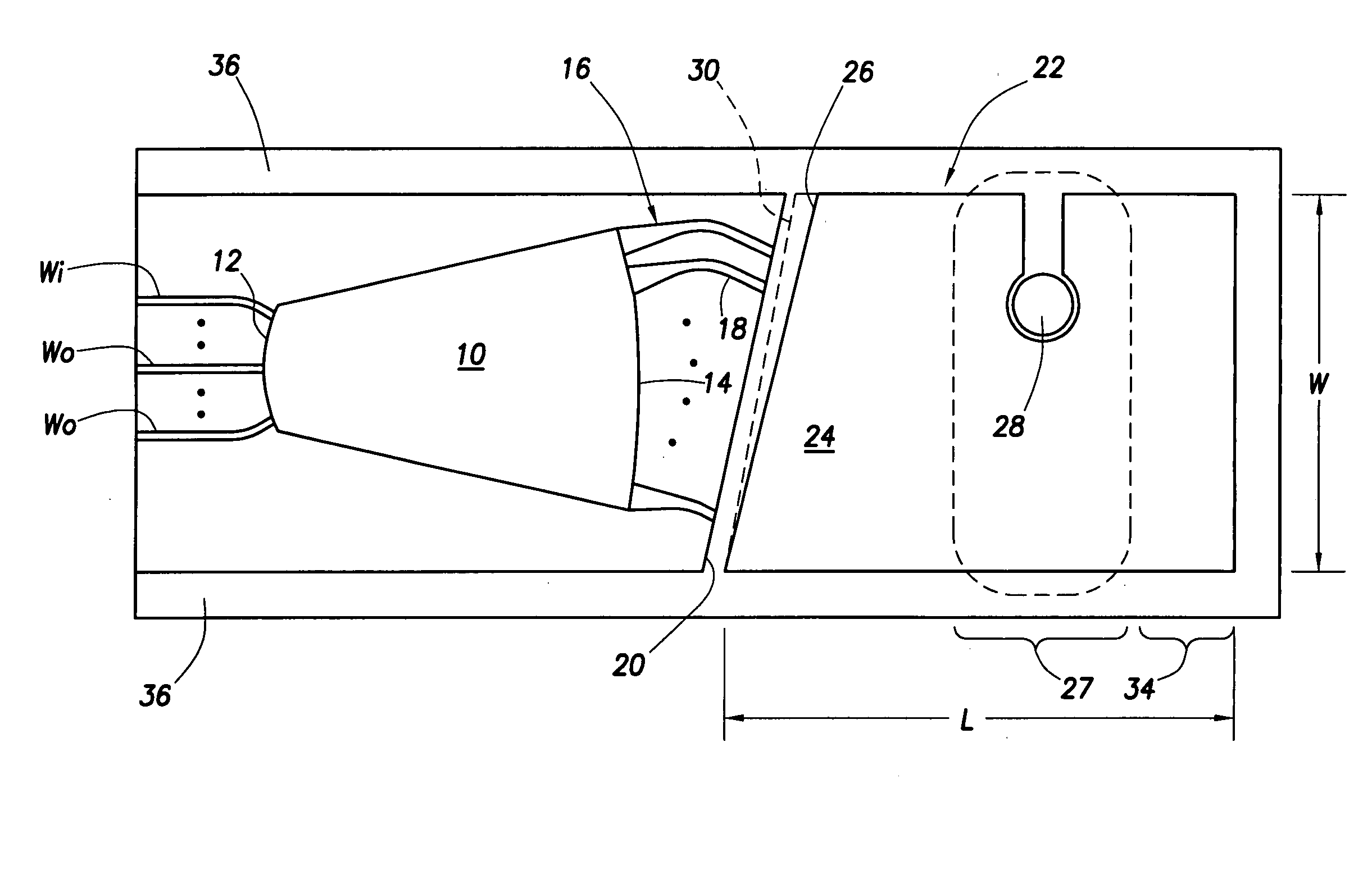
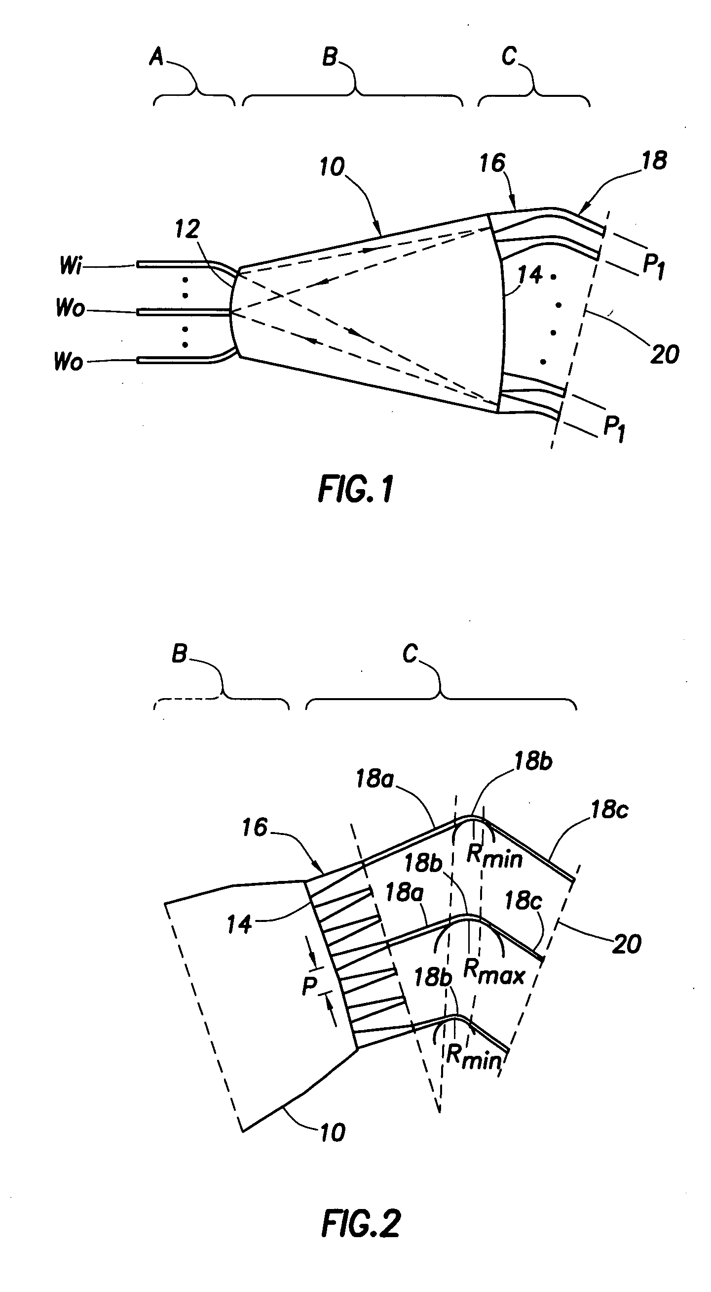
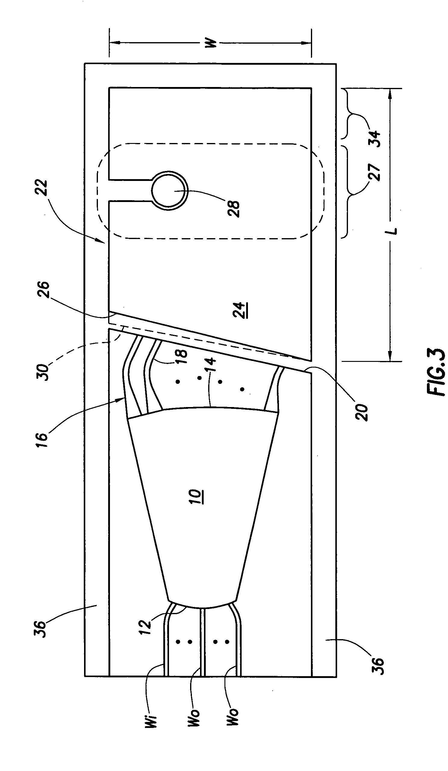
[0008] The problems noted above are solved in large part by an optical multiplexer that compensates for temperature effects by rotating a reflector surface optically coupled to grating waveguides of the multiplexer. The rotation of the reflector surface is based on differential thermal expansion. Some exemplary embodiments may comprise a waveguide sections and a mirror assembly rigidly coupled to a common silicon submount. A portion of the mirror assembly between the reflector surface and where the mirror assembly is rigidly attached to the submount deforms as a function of temperature to change an angle between the optical waveguide grating and the reflector surface.
[0009] The disclosed devices and methods comprise a combination of features and advantages which enable it to overcome the deficiencies of the prior art devices. The various characteristics described above, as well as other features, will be readily apparent to those skilled in the art upon reading the following detailed description, and by referring to the accompanying drawings.

Problems solved by technology

However, the index of refraction within the waveguides changes with operating temperature, which therefore changes the optical path lengths and adversely affects operation.
Precise temperature control may be difficult and costly, particularly in remote locations.
However, it is difficult to rotationally mount the mirror on the substrate, and further the thermally conductive body pushing on the reflective surface and the substrate tends to distort the mirror and produce stress in the grating, degrading performance.

Method used


Image

  • Temperature compensated optical multiplexer
  • Temperature compensated optical multiplexer
  • Temperature compensated optical multiplexer

Examples


Embodiment Construction

[0008] The problems noted above are solved in large part by an optical multiplexer that compensates for temperature effects by rotating a reflector surface optically coupled to grating waveguides of the multiplexer. The rotation of the reflector surface is based on differential thermal expansion. Some exemplary embodiments may comprise a waveguide sections and a mirror assembly rigidly coupled to a common silicon submount. A portion of the mirror assembly between the reflector surface and where the mirror assembly is rigidly attached to the submount deforms as a function of temperature to change an angle between the optical waveguide grating and the reflector surface.

[0009] The disclosed devices and methods comprise a combination of features and advantages which enable it to overcome the deficiencies of the prior art devices. The various characteristics described above, as well as other features, will be readily apparent to those skilled in the art upon reading the following detail...


PUM


Abstract

An optical multiplexer that adjusts the wavelength response and compensates for temperature effects by using rotatable mirror. The wavelength response of the device is adjusted by aligning the mirror at a correct angle with respect to the surface terminating the optical waveguide grating. The temperature dependence of the index of refraction of the material comprising the waveguides is compensated for by rotating a reflecting surface of the mirror, the rotation based on differential thermal expansion. Some exemplary embodiments may comprise a slab waveguide on a substrate (the slab waveguide having a first and second arcuate end surfaces) attached to a submount, a mirror assembly rigidly attached to the submount (the mirror assembly comprising a first and second materials having different coefficients of thermal expansion), and an optical waveguide grating (upon the substrate attached to the submount) optically coupled between the second arcuate surface and the mirror assembly. A portion of the mirror assembly between the reflector surface and where the mirror assembly is rigidly attached to the submount deforms as a function of temperature to change an angle between the optical waveguide grating and the reflecting surface.

Description

CROSS-REFERENCE TO RELATED APPLICATIONS [0001] This application claims the benefit of provisional application Ser. No. 60 / 540,941 filed Jan. 30, 2004 and titled, “Temperature compensated optical multiplexer,” which application is incorporated by reference herein as if reproduced in full below.STATEMENT REGARDING FEDERALLY SPONSORED RESEARCH OR DEVELOPMENT [0002] Not applicable. BACKGROUND OF THE INVENTION [0003] 1. Field of the Invention [0004] Various embodiments of the invention are directed to temperature compensated optical multiplexers. More particularly, embodiments of the invention are directed to a reflective arrayed waveguide grating multiplexer having a mirror that rotates based on differential thermal expansion to compensate for differences in index of refraction caused by temperature changes. [0005] 2. Discussion of the Related Art [0006] Optical multiplexers may comprise waveguides within which light of varying frequencies is allowed to propagate. However, the index of ...

Claims


Application Information

Patent Timeline
Patent Type & Authority Applications(United States)
IPC IPC(8): G02B6/34
CPCG02B6/1203G02B6/12011
Inventor TEMKIN, HENRYKGRAVE DE PERALTA, LUIS E.BERNUSSI, AYRTON A.GORBOUNOV, VALERI
Owner TEXAS TECH UNIVERSITY
Learn More