Dispersion slope equalizer

a technology of dispersion slope and equalizer, which is applied in the direction of multiplex communication, instruments, optical elements, etc., can solve the problems of limiting the transmission capacity or propagation distance (distance between repeaters), the inability to compensate for the dispersion slope of dsf or nz-, and the inability to compensate for the dispersion of various fiber transmission lines

Inactive Publication Date: 2005-08-04
NIPPON TELEGRAPH & TELEPHONE CORP
View PDF5 Cites 8 Cited by
  • Summary
  • Abstract
  • Description
  • Claims
  • Application Information

AI Technical Summary

Benefits of technology

[0012] Considering the foregoing problems, an object of the present invention is to provide a compact dispersion slope equalizer by which it is possible to simultaneously recover distorted waveforms of WDM signals by dispersion slope of DSF or NZ-DSF at 1.55 μm band, and to compensate for the dispersion of various fiber transmission lines having various dispersion values and variation of dispersion value caused by the temperature change or the like. This configuration comprises group delay controllers comprising lattice-form optical circuits, transversal-form optical circuits, or the combination of these two circuits.

Problems solved by technology

As a result, the signal pulse at each wavelength channel is differently distorted, which limits the transmission capacity or propagation distance (distance between repeaters).
However, the prior art dispersion slope equalizer having the foregoing configuration has following problems: (1) by utilizing the foregoing configuration, it is possible to compensate for dispersion slope of a 1.3 μm band zero dispersion fiber (that is; single mode fiber (SMF)) at 1.55 μm band, but it is impossible to compensate for dispersion slope of DSF or NZ-DSF at 1.55 μm band, (2) configuration is complicated and the size is large, and (3) compensation value is fixed, and it is impossible to compensate for the dispersion of various fiber transmission lines having various dispersion values and variation of dispersion value caused by the temperature change or the like by utilizing the foregoing configuration.

Method used


Image

  • Dispersion slope equalizer
  • Dispersion slope equalizer
  • Dispersion slope equalizer

Examples


first embodiment

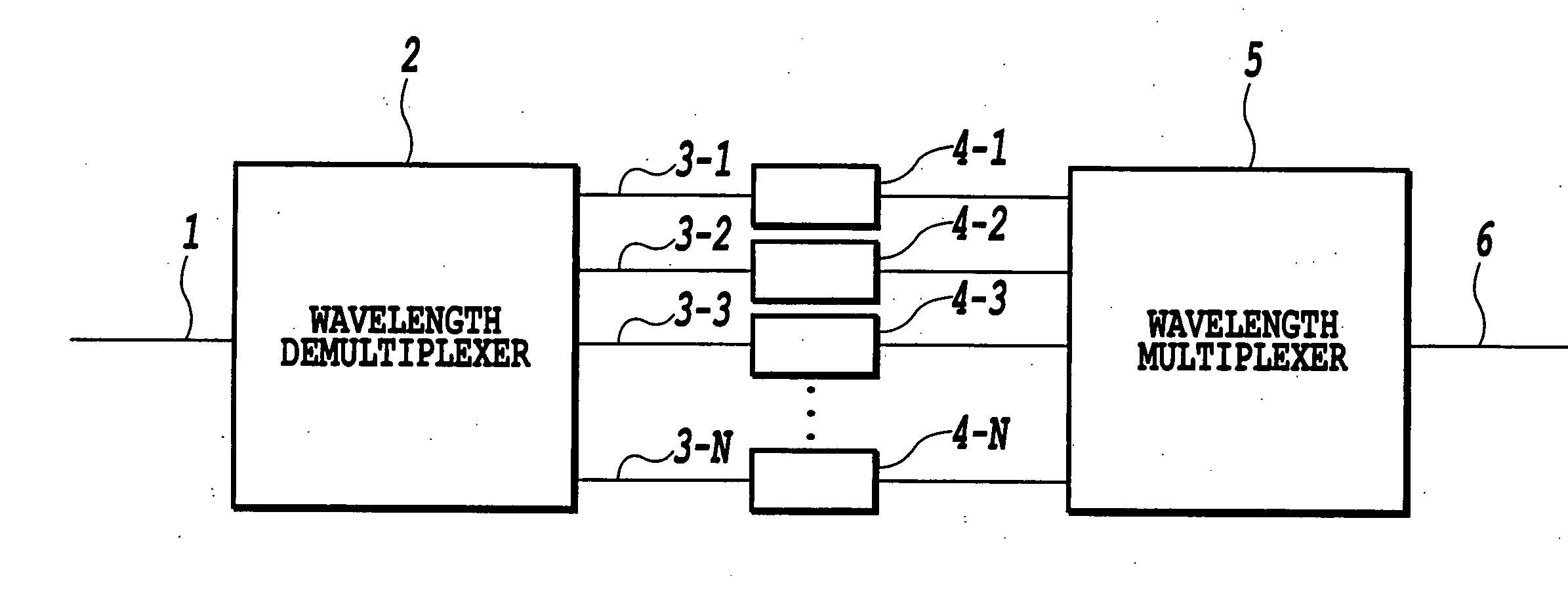
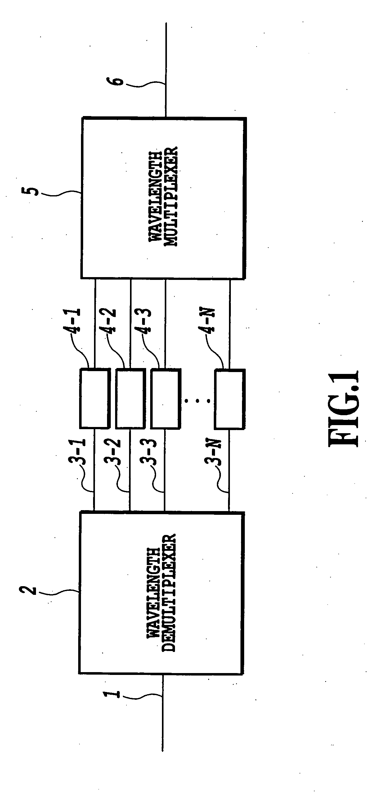
[0050]FIG. 1 is a diagram showing the configuration of a first embodiment of the dispersion slope equalizer according to the present invention; [0051] In FIG. 1, the dispersion slope equalizer of the present embodiment comprises an input waveguide 1, a wavelength demultiplexer 2, waveguides 3-1 to 3-N, lattice-form optical circuits 4-1 to 4-N, a wavelength multiplexer 5, and an output waveguide 6.

[0052] WDM signal lightwaves λ1 to kN distorted by the dispersion slope are introduced into the input waveguide 1 and are demultiplexed by the wavelength demultiplexer 2 into wavelength components. Then, these wavelength components are introduced into the lattice-form optical circuits 4-1 to 4-N for dispersion slope compensation, and are multiplexed by the wavelength multiplexer 5. Finally, the multiplexed lightwaves are outputted at the output waveguide 6, thus achieving the dispersion slope equalizer.

[0053] The wavelength demultiplexer 2 and the wavelength multiplexer 5 can be composed ...

second embodiment

[0078]FIG. 9 is a diagram showing the configuration of a second embodiment of the dispersion slope equalizer according to the present invention.

[0079] In FIG. 9, the dispersion slope equalizer of the present embodiment comprises an input waveguide 14, a wavelength demultiplexer 15, waveguides 16a to 16h, lattice-form optical circuits 17a and 17b, a wavelength multiplexer 18, and an output waveguide 19. Both of the waveguides 7a and 7b in FIG. 2 and two of the waveguides 16a to 16d, and both of the waveguides 7e and 7f and two of the waveguides 16e to 16h are connected.

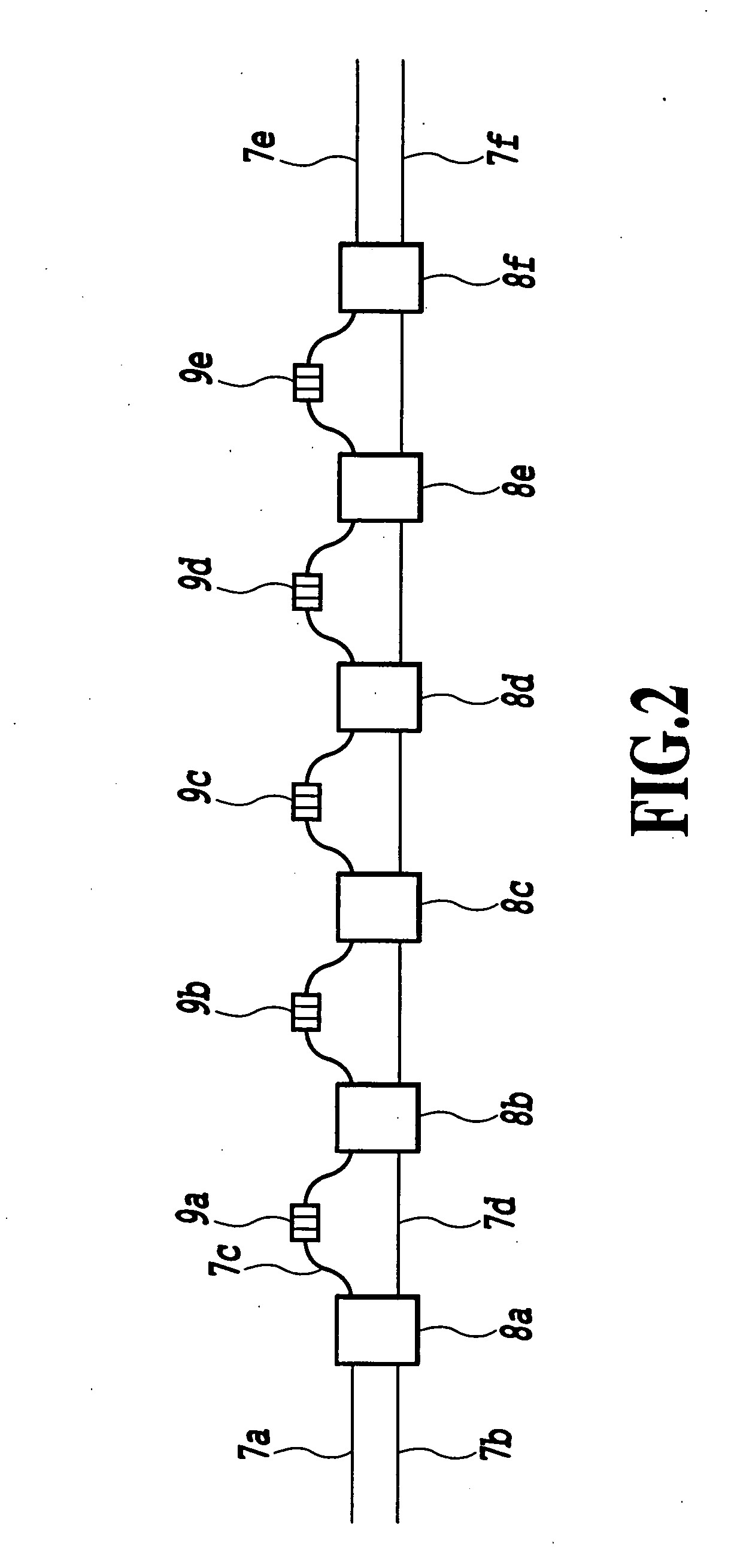
[0080] In the lattice-form optical circuits in FIG. 2, it is confirmed that dispersion characteristic between two sets of input / output ports, for example, dispersion characteristics between the input waveguide 7a and the outputwaveguide 7e and between the input waveguide 7b and the output waveguide 7f have the same absolute value with opposite sign. This was confirmed because a transfer matrix of the lattice-form opt...

third embodiment

[0089]FIG. 14 is a diagram showing the configuration of a third embodiment of the dispersion slope equalizer according to the present invention.

[0090] In FIG. 14, the dispersion slope equalizer of the present embodiment comprises an input waveguide 20, a wavelength demultiplexer 21, waveguides 22-1 to 22-N, transversal-form optical circuits 23-1 to 23-N, a wavelength multiplexer 24, and an output waveguide 25.

[0091]FIG. 15 is a diagram showing a configuration example of the transversal-form optical circuits 23-1 to 23-N.

[0092] The transversal-form optical circuits 23-1 to 23-N have the following configuration. The lightwaves are introduced into the input waveguide 26a or 26b, and then are tapped at eight taps 27a to 27h, and are finally multiplexed again by the multiplexer 29 into the output waveguide 30. Numerals 26a to 26i and 28a to 28h are waveguides and waveguide control parts of refractive index, respectively. One of the waveguides 26a and 26b and the output waveguide 30 ar...


PUM


Abstract

The object of the present invention is to provide a compact dispersion slope equalizer by which it is possible to simultaneously recover distorted waveforms of WDM signals by dispersion slope of DSF or NZ-DSF at 1.55 μm band, and to compensate for the dispersion of various fiber transmission lines having various dispersion values and variation of dispersion value caused by the temperature change or the like. WDM signals distorted by the dispersion slope of the fiber are introduced into an input waveguide, and are demultiplexed by a wavelength demultiplexer into each wavelength component, and pass through lattice-form optical circuits, transversal-form optical circuits, or the combination of these circuits. The dispersion slope of the signals is compensated for by these circuits. The recovered signals are multiplexed by a wavelength multiplexer, and the multiplexed light is outputted at an output waveguide. Arrayed-waveguide gratings can be used as the wavelength demultiplexer and multiplexer. Also, cascaded configuration of Mach-Zehnder interferometers, bulk-type optical filters, or fiber-type (or waveguide-type) gratings in series can also be used as the wavelength demultiplexer and multiplexer.

Description

[0001] This application is based on Patent Application No. 11-296877(1999) filed Oct. 19, 1999 in Japan, the content of which is incorporated hereinto by reference. BACKGROUND OF THE INVENTION [0002] 1. Field of the Invention [0003] The present invention is on a dispersion slope equalizer that simultaneously recovers waveforms of wavelength division multiplexed (WDM) signals distorted by dispersion characteristic (that is; group delay is different at each wavelength) in an optical fiber. [0004] 2. Description of the Related Art [0005] Today, the investigation to achieve a large capacity optical transmission systems is being actively carried out utilizing a dispersion shifted fiber (DSF) having zero dispersion or a non-zero dispersion shifted fiber (NZ-DSF) having several psec / nm / km dispersion at wavelength λ=1.55 μm band. [0006] However, when WDM transmission using DSF's is carried out in order to realize large capacity networks, second-order dispersion (derivative of group delay wi...

Claims


Application Information

Patent Timeline
Patent Type & Authority Applications(United States)
IPC IPC(8): G02B6/34H04B10/2513
CPCG02B6/12007G02B6/12021G02B6/29353G02B6/29355H04B2210/258G02B6/29395G02B6/29398H04B10/25133G02B6/29394
Inventor TAKIGUCHI, KOICHIOKAMOTO, KATSUNARIGOH, TAKASHI
Owner NIPPON TELEGRAPH & TELEPHONE CORP
Why Eureka
Try Eureka