Applicator

a technology of ink absorber and ink reservoir, which is applied in the field of ink absorber, can solve the problems of slow ink flow from the ink reservoir to the application body, difficult to form the sectional shape of the ink absorber, and inability to absorb ink, etc., and achieves the effect of preventing excessive flow or “gobbing” of ink, preventing drip, and large ink

Inactive Publication Date: 2005-08-04
PENTEL KK
View PDF3 Cites 9 Cited by
  • Summary
  • Abstract
  • Description
  • Claims
  • Application Information

AI Technical Summary

Benefits of technology

[0010] This invention has been made in the light of the above described problems. Accordingly, an object of this invention is to provide an applicator which hardly causes ink leakage such as ink drip under various usage or storage environmental conditions, even when using not only water-based ink but also oil-based ink, and which is of high quality enough to maintain appropriate ink delivery even when writing is carried out at high speeds.
[0011] Another object of this invention is to provide an applicator which can remove troubles such as thin spots caused by insufficient feeding of ink from the ink reservoir to the application body (nib body), which temporarily occur in continuous writing when pursuing the solution to the above problems.

Problems solved by technology

This gives rise to a problem of the flow of ink fed from the ink reservoir to the application body becoming slow, because it is a general physical phenomenon that the viscosity resistance of ink passing through a small-diameter ink flow path increases as the length of the ink flow path increases.
And when intending to increase the diameter of the ink flow path so as to overcome the problem, an adverse effect is produced of decreasing the area in the barrel's inside / transverse section in which the ink absorber is to be installed, thereby relatively decreasing the capacity for absorbing ink, or of making it hard to form the sectional shape of the ink absorber.
Thus there remains many difficulties in increasing the capacity of the ink absorber in a raw-ink applicator in which the inside diameter of its barrel is set at a prescribed thickness or in producing an applicator whose ink capacity is large.
In addition, there remain other problems in applicators which use such an ink absorber, such as insufficient drip-preventive performance.
If gas expansion takes place in the barrel under these conditions due to environmental changes and ink is pushed out from the ink reservoir, ink drips from the application body since the capability of the ink absorber to absorb the overflowing ink is insufficient.
Accordingly, even if the ink absorber can absorb the ink pushed out from the ink reservoir at the time of gas expansion, the absorbed ink can sometimes remain in the ink absorber, and the absorber cannot be restored to the state before absorption even at the time of gas contraction.
In such a case, when removing the cap fitted on the barrel to close the same, for example, the gas in the barrel expands so promptly that the ink absorber cannot absorb and hold the ink, resulting in occurrence of the drip of ink.

Method used


Image

  • Applicator
  • Applicator
  • Applicator

Examples


example 1

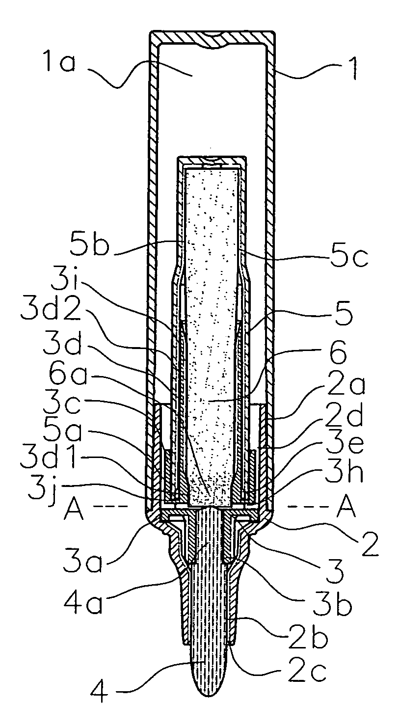
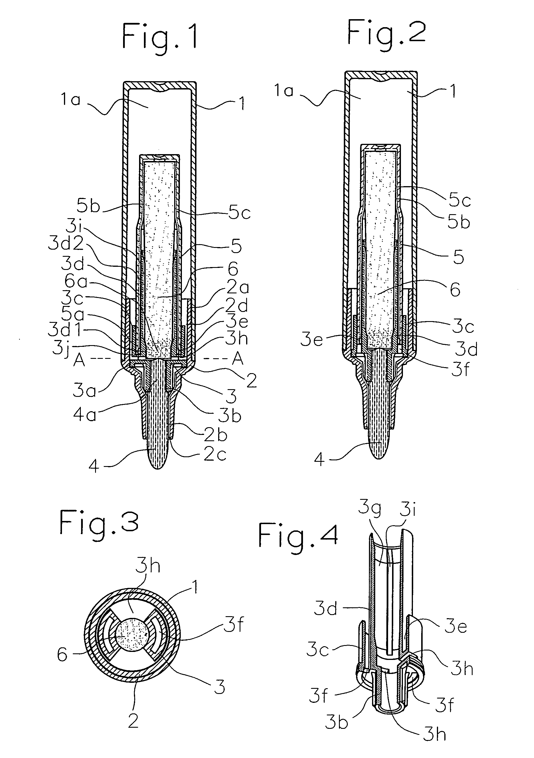
[0038]FIGS. 1-4 show an applicator in accordance with example 1 of this invention. FIG. 1 is a longitudinal sectional view of the applicator in accordance with example 1, FIG. 2 is a view of the applicator of FIG. 1, when it is rotated about its axis by 90 degrees, FIG. 3 is an enlarged transverse sectional view taken along the line A-A of FIG. 1, and FIG. 4 is a perspective view of the joint member of example 1. Reference numeral 1 denotes a rear barrel whose rear end portion is closed to use its interior as an ink reservoir 1a and fill the same with ink and whose front end portion is close fitted on the outside circumference portion 2a of a front barrel 2.

[0039] The front barrel 2 is closely fitted on the partition flange portion 3a of a joint tube 3 in the inside circumference portion, which will be described in detail presently, to divide itself into two: a rear barrel portion as an ink reservoir; and a front barrel portion as an attachment portion to which an applicator body 4...

example 2

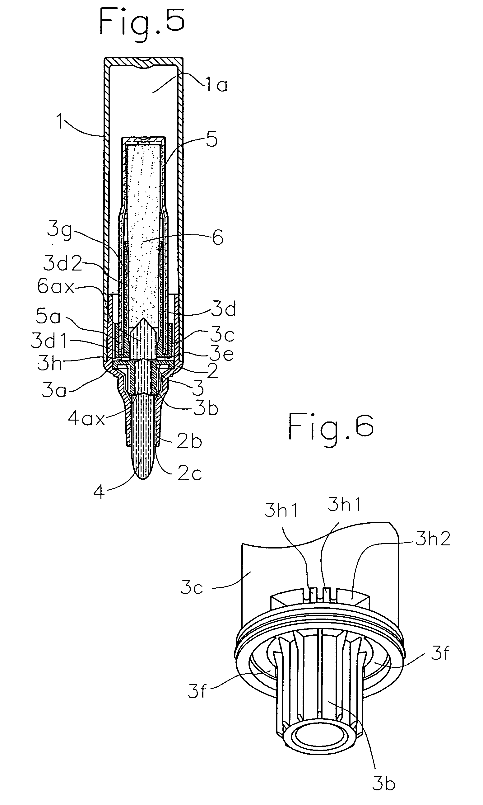
[0056] An applicator in accordance with example 2 of this invention is shown in FIG. 5, which is a longitudinal sectional view of the applicator in accordance with this example. The applicator of example 2 is the same as that of example 1, except that part of the materials used for the ink flow path is changed. The function / action obtained are the same as those of example 1; however, this example is shown byway of example that provides a wider choice when manufacturing applicators, in particular, provides, for example, improved dimensional precision with which materials used for parts are processed and improved capillary force (or density) precision. Parts that are in common with those of example 1 are denoted with the same reference numerals.

[0057] In a rear barrel 1, its rear end portion is closed to use its interior as an ink reservoir 1a and fill the same with ink and its front end portion is close fitted on a front barrel 2. The front barrel 2 is closely fitted on the partitio...

example 3

[0066] A joint tube in accordance with example 3 of this invention is shown in FIG. 6, which is an enlarged view showing the main part of the joint tube in accordance with example 3. The ink connecting opening 3h is a penetration which connects the outside circumference portion of the outer tube 3c and the inner tube 3d radially by a partition wall 3j which blocks part of the cross section of the ventilation annulus 3e. AS shown in FIGS. 6 and 7, the shape of the opening is such that irregular ribs with concavo-convex portions are formed on the middle upper portion of the opening wall, the convex portion 3h1 of the ribs is provided with a narrow clearance while the concave portion 3h2 of the same with a wide clearance so that the capillary action is strong in the convex portion 3h1 while the capillary action weak in the concave portion 3h2, and the size of the outermost part of the ink connecting opening 3h is large in the periphery and gradually decreased towards the inner part of ...


PUM


Abstract

To provide an applicator which is free from ink leakage under any usage-environmental conditions, is suitable for oil-based ink, maintains appropriate ink delivery and is produced at low cost. The applicator in accordance with this invention is a raw-ink applicator of an automatic delivery type, wherein, with the application body facing downward, an ink flow path on the application body side is arranged on the lower side relative to the ink connecting opening of the ink reservoir while an ink flow path on the ink absorber side and a ventilation annulus are arranged on the upper side relative to the ink connecting opening, the ink absorber is divided into two so that it communicates with the ink in the ink reservoir only in the opening of the ink connection opening, and in the ink flow path the relation, A<B<C, holds, where A represents the density of the rear portion of the flow path on the ink absorber side, B represents the density of the front portion of the flow path on the ink absorber side, and C represents the density the ink flow path on the application body side.

Description

TECHNICAL FIELD [0001] This invention relates to an applicator which includes a raw-ink tank for containing a liquid material (hereinafter referred to as ink) such as water-based (water-soluble) or oil-based writing ink for writing utensils, jet printing ink, cosmetic liquid such as eyeliner, or coating liquid such as paint or drug; and a mechanism for automatically controlling the delivery of ink in response to coating, writing or recording. BACKGROUND OF THE INVENTION [0002] A writing utensil has been known which automatically controls the delivery of raw ink, specifically which includes an ink reservoir in its barrel and replenishes its application body (nib body) with ink contained in the ink reservoir successively with the consumption of ink in writing or coating so that writing or coating can be performed continuously. For example, Japanese Utility Model Publication No. 60-69690 describes a raw-ink delivery controlling mechanism that includes an ink absorber arranged in the in...

Claims


Application Information

Patent Timeline
Patent Type & Authority Applications(United States)
IPC IPC(8): A45D34/04B43K5/18B43K8/03B43K8/04B43K27/08
CPCA45D34/042A45D2200/1018A46B2200/1046B43K27/08B43K8/03B43K8/04B43K5/18
Inventor YAMADA, NORIOOTA, RYUSUKE
Owner PENTEL KK
Why Eureka
Try Eureka