
Hydraulic gravity ram pump

Inactive Publication Date: 2005-08-04
MCNICHOL RICHARD FREDERICK
View PDF15 Cites 24 Cited by
  • Summary
  • Abstract
  • Description
  • Claims
  • Application Information

AI Technical Summary

Benefits of technology

[0012] The invention offers significant advantages compared with conventional pumps for deep wells, pumping out mines and other applications for pumping liquids up relatively high hydraulic heads, such as energy recovery at hydro dams. It allows the use of a pump which requires far less energy input to pump liquids up significant vertical distances because it converts the potential energy of the standing column into kinetic energy. At the same time, it overcomes disadvantages associated with prior art pumps of the general type by increasing its efficiency significantly by comparison. Thus the invention is attractive for commercial applications where prior art devices have not proven to be viable.

Problems solved by technology

Pumping liquids against substantial hydraulic heads is a problem encountered in pumping out mines, deep wells, and similar applications such as pumping water back up, over a hydro dam during low energy usage periods, for subsequent recovery during high energy usage periods, and for use in run-of-the-river hydro power applications utilizing the potential energy of water in a standing column.
However such earlier devices have not been efficient enough to justify their commercial usage.

Method used


Image

  • Hydraulic gravity ram pump
  • Hydraulic gravity ram pump
  • Hydraulic gravity ram pump

Examples


Embodiment Construction

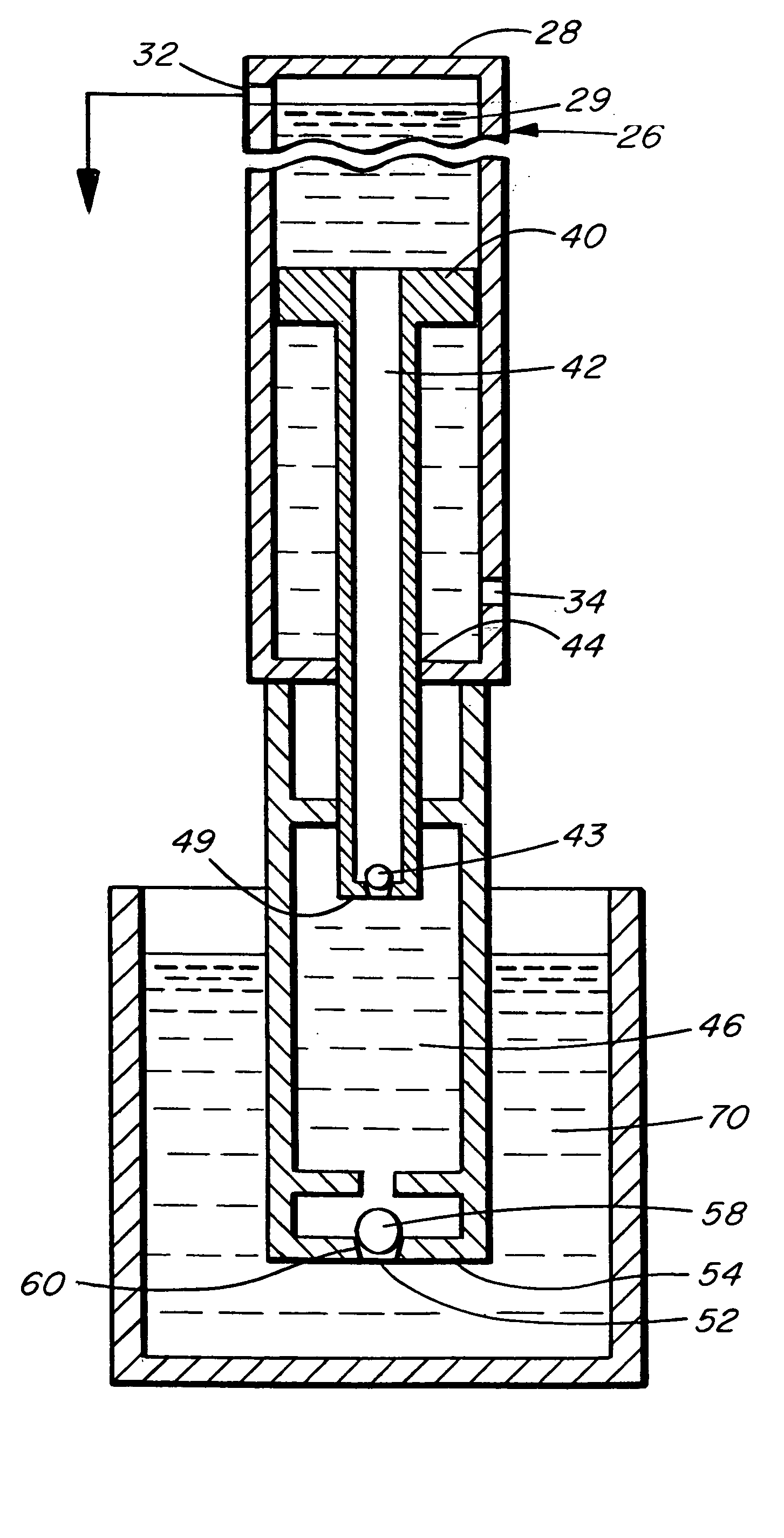
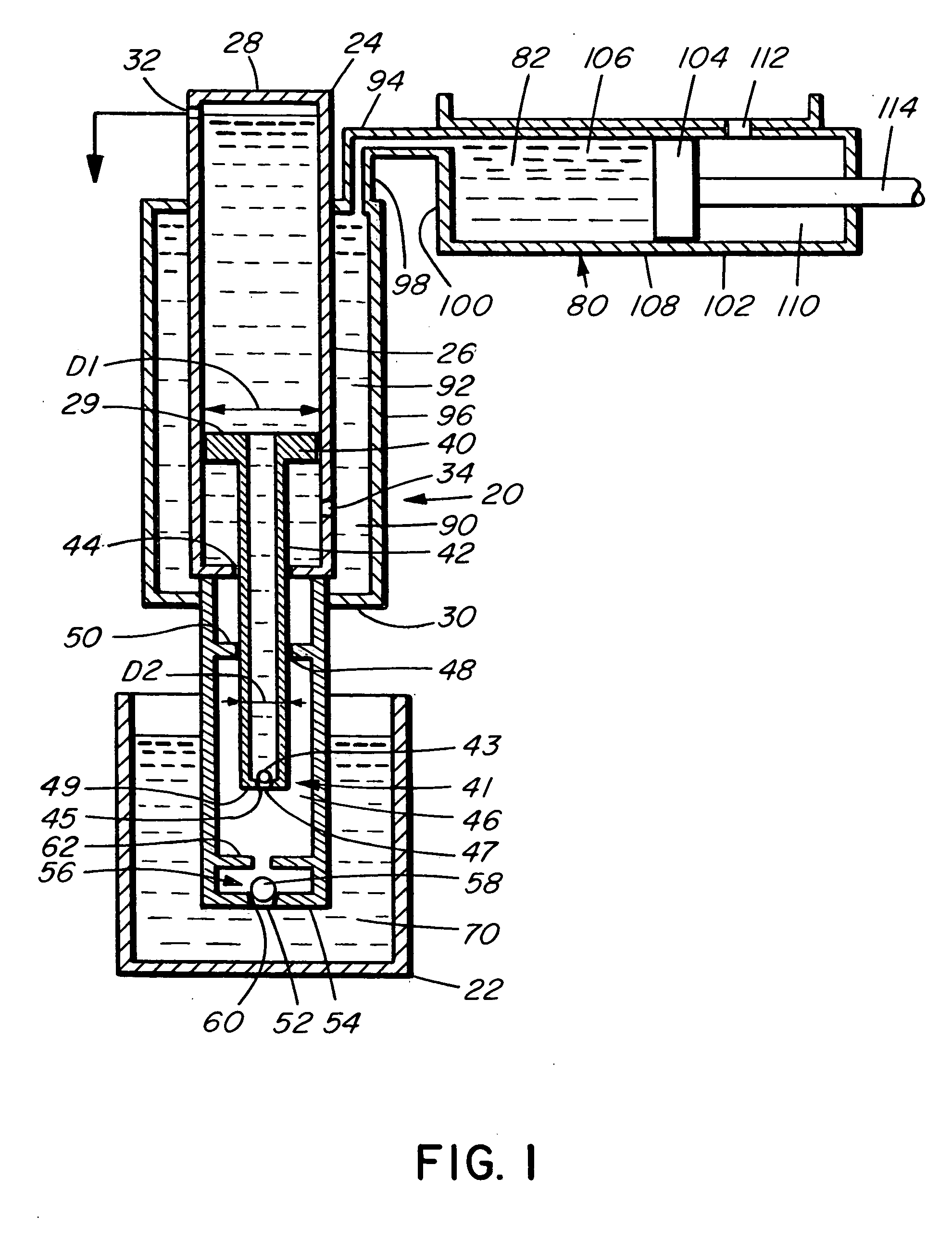
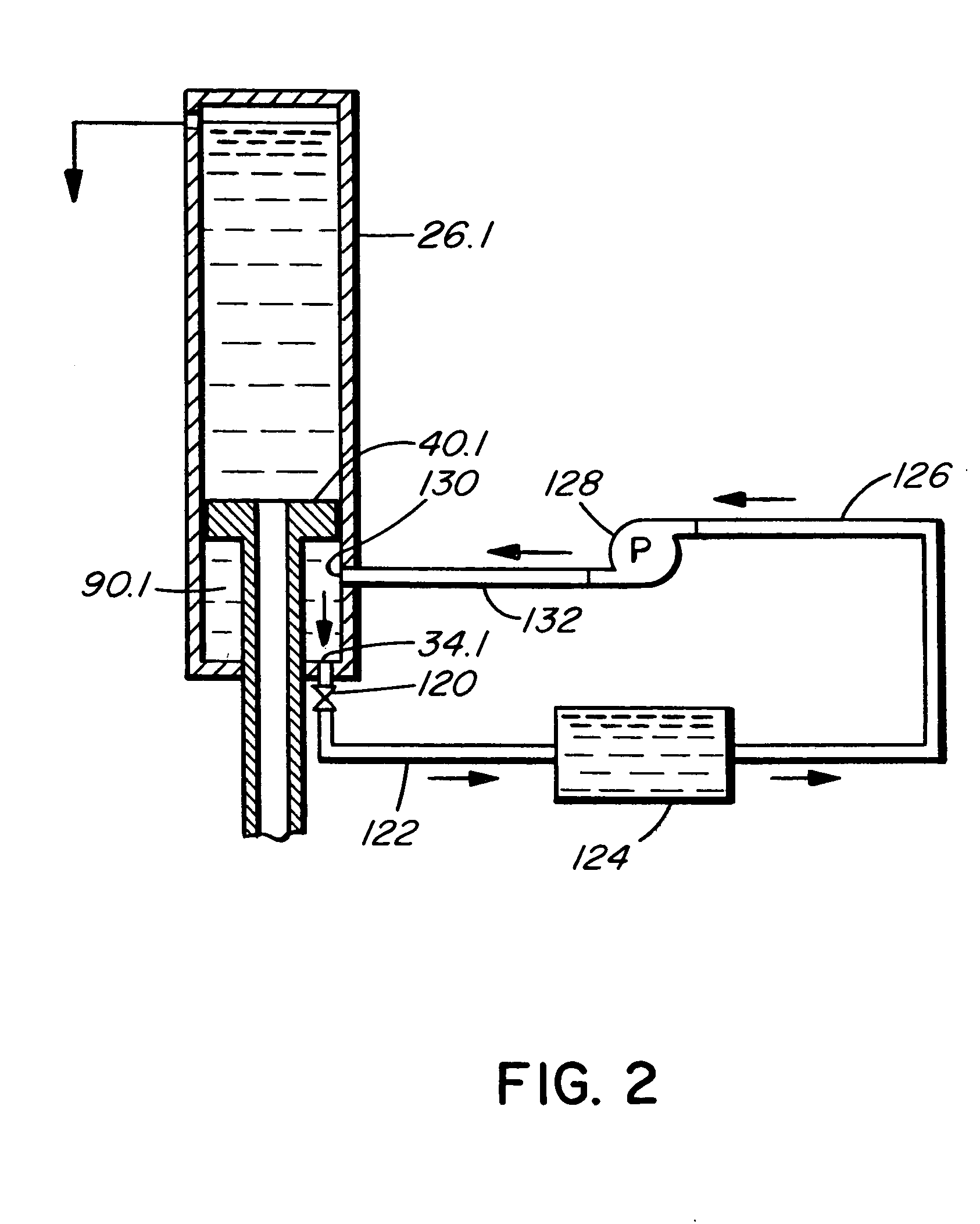
[0019] Referring to the drawings, and first to FIG. 1, this shows a piston type pumping apparatus 20 according to an embodiment of the invention. The apparatus is intended to pump liquids, typically water, up relatively great vertical distances, such as from the bottom of a mine to the surface as exemplified by the distance between points 22 and 24. The system includes a vertically oriented first transfer cylinder 26 having a top 28, adjacent point 24, and a bottom 30. There is a first passageway 32 for liquid adjacent the top where liquid is discharged from the cylinder. There is a second passageway 34 near the bottom of the cylinder which allows liquid to enter or exit the cylinder.

[0020] A transfer piston 40 is reciprocatingly mounted within the cylinder and is connected to a vertically oriented, hollow piston rod 42 which extends slidably and sealingly through aperture 44 in the bottom of the cylinder. The piston 40 has an area 29 at the top thereof against which pressurized fl...


PUM


Abstract

A piston type pumping apparatus comprises a vertically oriented cylinder having a top and a bottom with a first passageway for liquid in the cylinder adjacent to the top thereof. There is a second passageway for liquid in the cylinder adjacent to the bottom thereof A piston is reciprocatingly mounted within the cylinder. A hollow piston rod is connected to the piston and extends slidably and sealingly through the bottom of the cylinder. There is a reload chamber below the cylinder, the piston rod extending slidably and sealingly into the reload chamber and having a third passageway for liquid communicating with the reload chamber. The piston rod has a smaller cross-sectional area within the reload chamber than the piston, whereby liquid in the cylinder acting downwardly on the piston exerts a greater force on the piston than liquid in the reload chamber acting against the piston rod. There is a first one-way valve located in the third passageway which permits liquid to flow from the reload chamber into the piston rod and prevents liquid from flowing from the piston rod into the reload chamber. A fourth passageway for liquid extends from the reload chamber to a source of liquid to be pumped. A second one-way valve in the fourth passageway permits liquid to flow from the source of liquid into the reload chamber and prevents liquid from flowing from the reload chamber towards the source of liquid. There is means for storing pressurized liquid connected to the second passageway for storing pressurized liquid displaced below the piston, as the piston moves downwardly, and to assist in raising the piston and, accordingly, liquid contained within the piston rod, to pump liquid upwardly and through the first passageway.

Description

BACKGROUND OF THE INVENTION [0001] This invention relates to pumps, and in particular to piston type pumps for pumping liquids to significantly higher elevations and pumps having energy recovery means. [0002] Pumping liquids against substantial hydraulic heads is a problem encountered in pumping out mines, deep wells, and similar applications such as pumping water back up, over a hydro dam during low energy usage periods, for subsequent recovery during high energy usage periods, and for use in run-of-the-river hydro power applications utilizing the potential energy of water in a standing column. [0003] A number of earlier patents attempt to provide devices which utilize a piston type pump where energy is recovered from a column of liquid acting downwardly on the piston, as the piston moves downwardly, in order to assist in subsequently raising the piston together with a volume of liquid to be pumped upwardly. An example of such an earlier patent is U.S. Pat. No. 6,193,476 to Sweeney...

Claims


Application Information

Patent Timeline
IPC IPC(8): F04B9/08F04B9/107F04B47/08F04B47/10F04F7/02
CPCF04B9/107F04B19/00F04B47/10F04B47/08F04B9/1076
Inventor MCNICHOL, RICHARD FREDERICK
Owner MCNICHOL RICHARD FREDERICK
Learn More