
Method and device for obtaining water from ambient air

Inactive Publication Date: 2020-11-05
AQUAHARA TECH GMBH
View PDF0 Cites 1 Cited by
  • Summary
  • Abstract
  • Description
  • Claims
  • Application Information

AI Technical Summary

Benefits of technology

The present invention provides a method and device for obtaining water from ambient air that is simpler, less expensive, and requires less energy input than known methods and devices. The cooling medium used in the device is a diluted absorbent solution that can be supplied to the evaporator and the condenser for cooling, and the heated cooling medium is then returned to the system for further cooling. The device can be operated with any type of liquid absorbent solution or a mixture of different solutions, and the cooling medium can be a liquid with low vapor pressure, such as oil. This invention allows for a more efficient and cost-effective operation of the device.

Problems solved by technology

All of the above mentioned methods and devices disadvantageously have a very high energy input, in particular of electrical energy.
If one would supply the known atmospheric water generators exclusively with regenerative energy, for example in desert regions, this would imply the necessity of a very large area of photovoltaic modules with correspondingly high cost per liter of the obtained water.
Therefore, heat from the following sources was employed heretofore for the operation of the known plants with evaporation devices: combustion of fossil fuels, with the known disadvantages for the environment; conventional thermal solar modules, often even with vacuum tubes, to be able to achieve correspondingly high temperatures and with correspondingly high plant cost; as well as condensation heat in the method of the so-called mechanical vapor recompression, for which much electrical energy is in turn required.
However, it is disadvantageous in this prior art that always an expensive, since corrosion-resistant, heat exchanger is used here as the pre-heating unit for the diluted sorbent.
Thereto, separate cooling devices arranged in the line system after the condenser are employed in conventional plants, which in turn increase the plant cost.

Method used


Image

  • Method and device for obtaining water from ambient air
  • Method and device for obtaining water from ambient air

Examples


Embodiment Construction

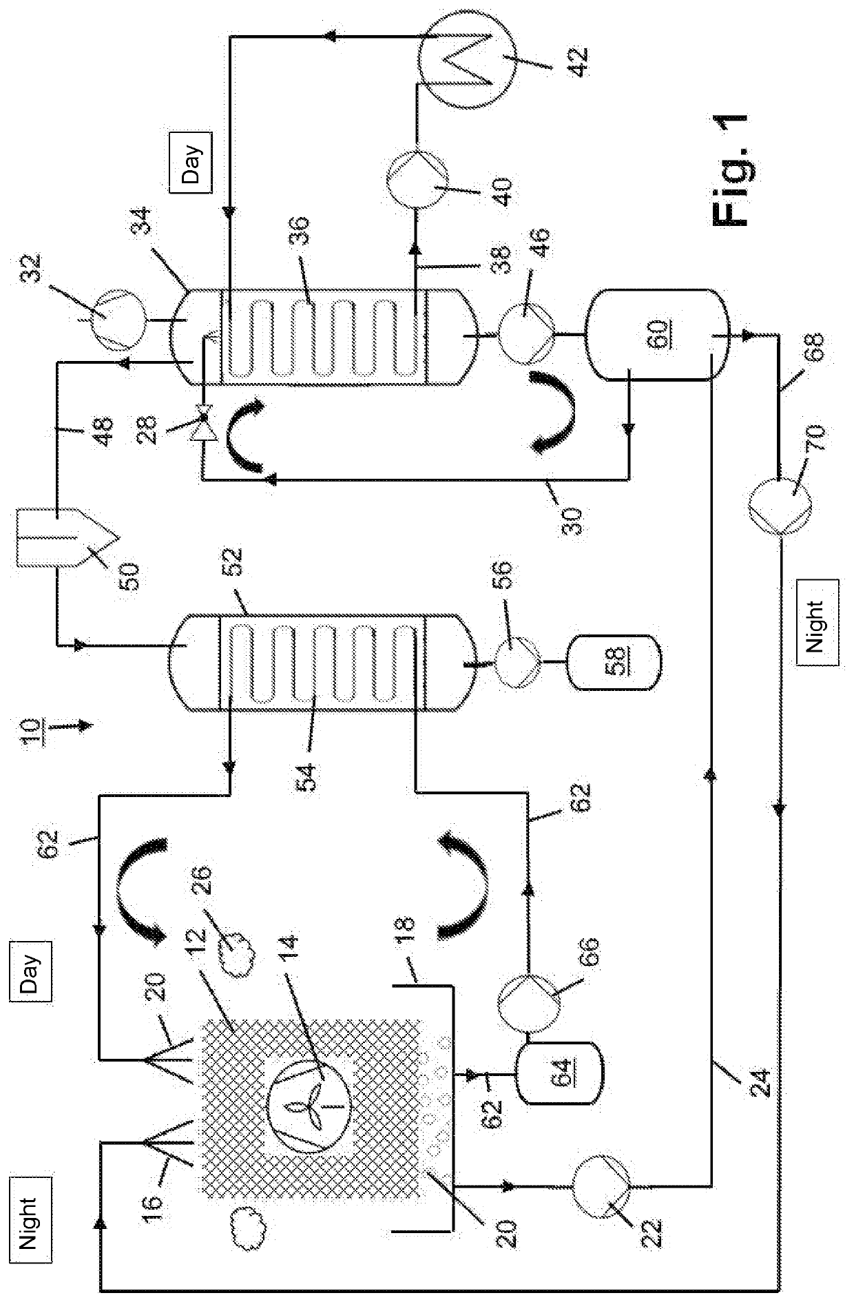
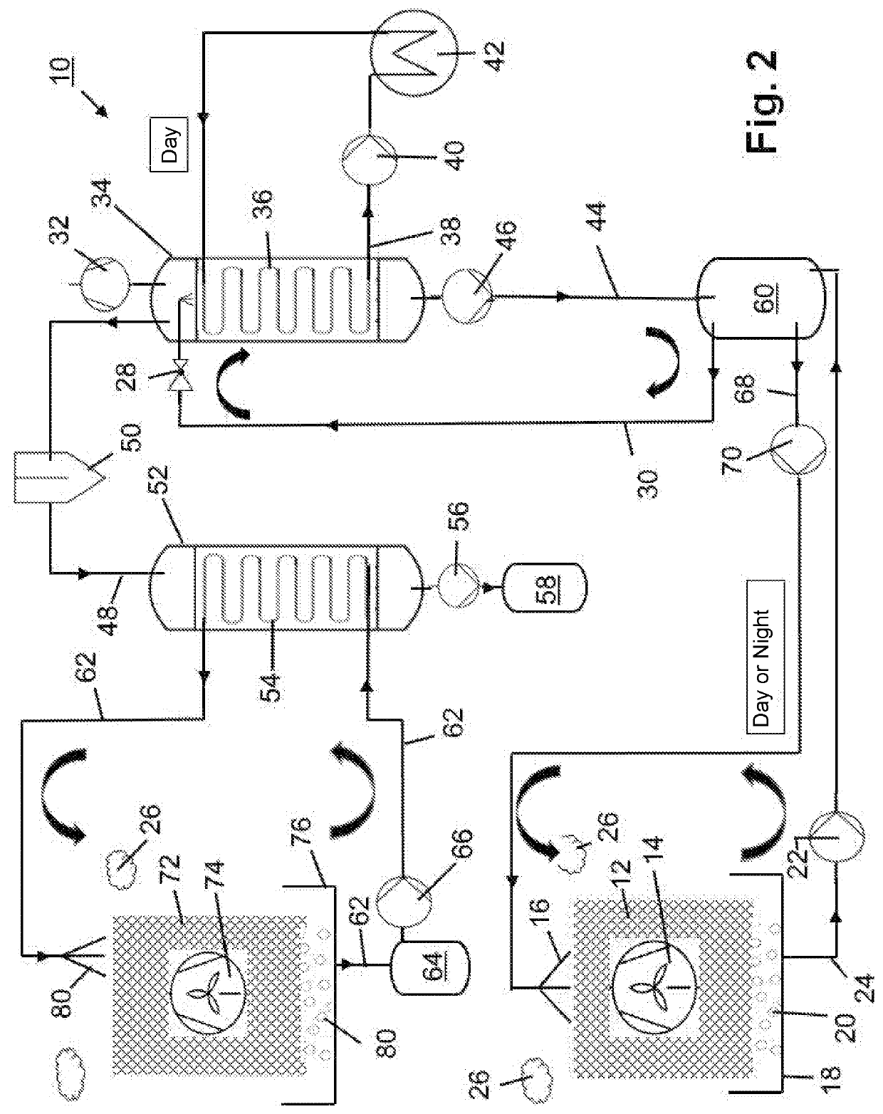
[0023]FIG. 1 shows a schematic representation of a device 10 for obtaining water from ambient air 26. In the illustrated first embodiment, the device 10 includes a device (not illustrated) for outputting a liquid absorbent 16 onto an absorption structure 12. In the illustrated first embodiment, the absorption structure 12 also represents a device for large-area contacting a cooling medium, as is explained in detail below. For applying or spreading the liquid absorbent 16, a suitable pipe system with corresponding openings or valves or comparative spraying devices can be used. Therein, the liquid absorbent 16 is in particular distributed over an entire upper surface of the absorption structure 12 and thus soaks the absorption structure 12. The absorbent 16 subsequently slowly flows into the lower areas of the absorption structure 12, where it again flows out of it and is again collected by a trough system 18. One recognizes that the absorption structure 12 is formed honeycombed in th...


PUM

PropertyMeasurementUnit
Timeaaaaaaaaaa
Hygroscopicityaaaaaaaaaa
Flow rateaaaaaaaaaa

Abstract

A method for obtaining water from ambient air, wherein the method contains at least the following method steps: contacting the ambient air with at least one liquid absorbent for absorbing at least a part of the water contained in the ambient air; conveying an absorbent diluted by the absorbed water to a first heat exchanger; transferring the diluted absorbent into at least one desorption device. Therein, water desorbed in the desorption device is conveyed to the first heat exchanger, wherein cooling of the desorbed water is effected by means of the diluted absorbent by means of the first heat exchanger. Furthermore, disclosed is a device for obtaining water from ambient air.

Description

FIELD[0001]The present invention relates to a method for obtaining water from ambient air. Furthermore, the invention relates to a device for obtaining water from ambient air.BACKGROUND[0002]Such methods and devices for obtaining water from ambient air are known in a great plurality. In particular, corresponding absorption methods are known from the air dehumidification technology. Therein, humidity from the air is absorbed in so-called liquid drying agents, for example in concentrated, hygroscopic salt solutions. A highly hygroscopic salt is e.g. lithium chloride. Subsequently, the water is partially again removed from the salt solution by heating, vacuum distillation, reverse osmosis or similar methods such that the solution can again be employed for dehumidifying the air. This method is for example industrially offered by the company Kathabar (see http: / / www.kathabar.com / liquid-desiccant / systen-features-benefits). Further systems, which are for example offered on the market under...

Claims


Application Information

Patent Timeline
IPC IPC(8): B01D53/26B01D53/28B01D5/00B01D53/18B01D53/14E03B3/28
CPCB01D53/185B01D53/1493E03B3/28B01D53/28B01D5/006B01D2252/10B01D5/0075B01D53/1425B01D5/0087B01D53/263B01D5/0003B01D5/0051B01D2259/65Y02A20/00
Inventor VERPLANCKE, PHILIPPE
Owner AQUAHARA TECH GMBH
Learn More