Hemostatic valve assembly

a valve assembly and hemisphere technology, applied in the field of medical devices, can solve the problems of less effective sealing of smaller diameter devices, less than optimal manner of engaging the ends of the seal to the respective hub and cap, and increased risk of fluid inward or outward leakag

Active Publication Date: 2005-08-04
COOK MEDICAL TECH LLC
View PDF67 Cites 145 Cited by
  • Summary
  • Abstract
  • Description
  • Claims
  • Application Information

AI Technical Summary

Benefits of technology

[0014] In still another version thereof, the present invention comprises an iris valve assembly for controlling a flow of fluid. The assembly comprises a base member, a rotatable member engaged with the base member in a manner to permit rotation of the rotatable member relative to the base member, and an elastomeric valve member having a longitudinal opening therethrough and having respective longitudinal ends. One of the longitudinal ends is secured to the base member and the other longitudinal end is secured to the rotatable member. The base member, rotatable member and valve member are aligned such that an elongated passageway is defined through the assembly. The base member and rotatable member are provided with complementary ratcheting members, which ratcheting members are aligned in a manner to inhibit recoil of the rotatable member relative to the base member following rotation of the rotatable member.

Problems solved by technology

As a result, the risk of inward or outward leakage of fluids has increased.
Such devices are generally effective for sealing large diameter devices, but are often less effective for sealing smaller diameter devices, particularly after the earlier passage of a large diameter device.
For example, the manner of engaging the ends of the seal to the respective hub and cap is less than optimal.
Such ends are capable of disengagement, which destroys the ability of the valve to form a seal.
In addition, the seal does not include provisions to prevent recoil of the seal after rotation of the rotatable cap to position the seal in a desired position.
Yet another problem with the iris valve assembly as described in the '553 patent is that longitudinally extending gaps or channels are capable of being formed along the seal, which gaps or channels can extend through the valve after rotation of the valve to the closed position.
When such gaps or channels are present, fluid can leak through them in the valve seal.
Furthermore, the configuration of such valves renders them subject to tearing.

Method used


Image

  • Hemostatic valve assembly
  • Hemostatic valve assembly
  • Hemostatic valve assembly

Examples


Embodiment Construction

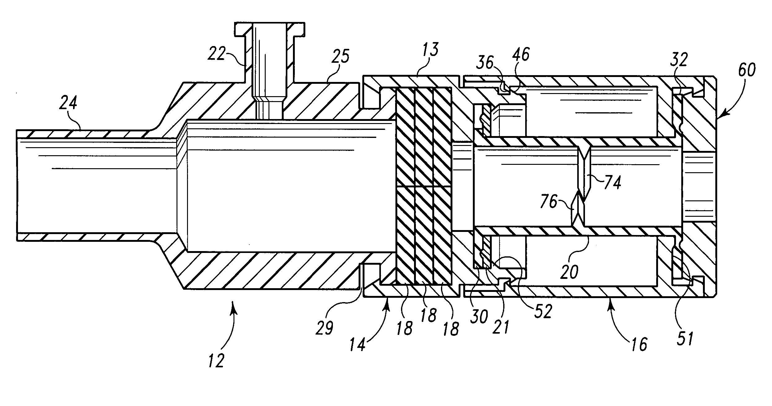
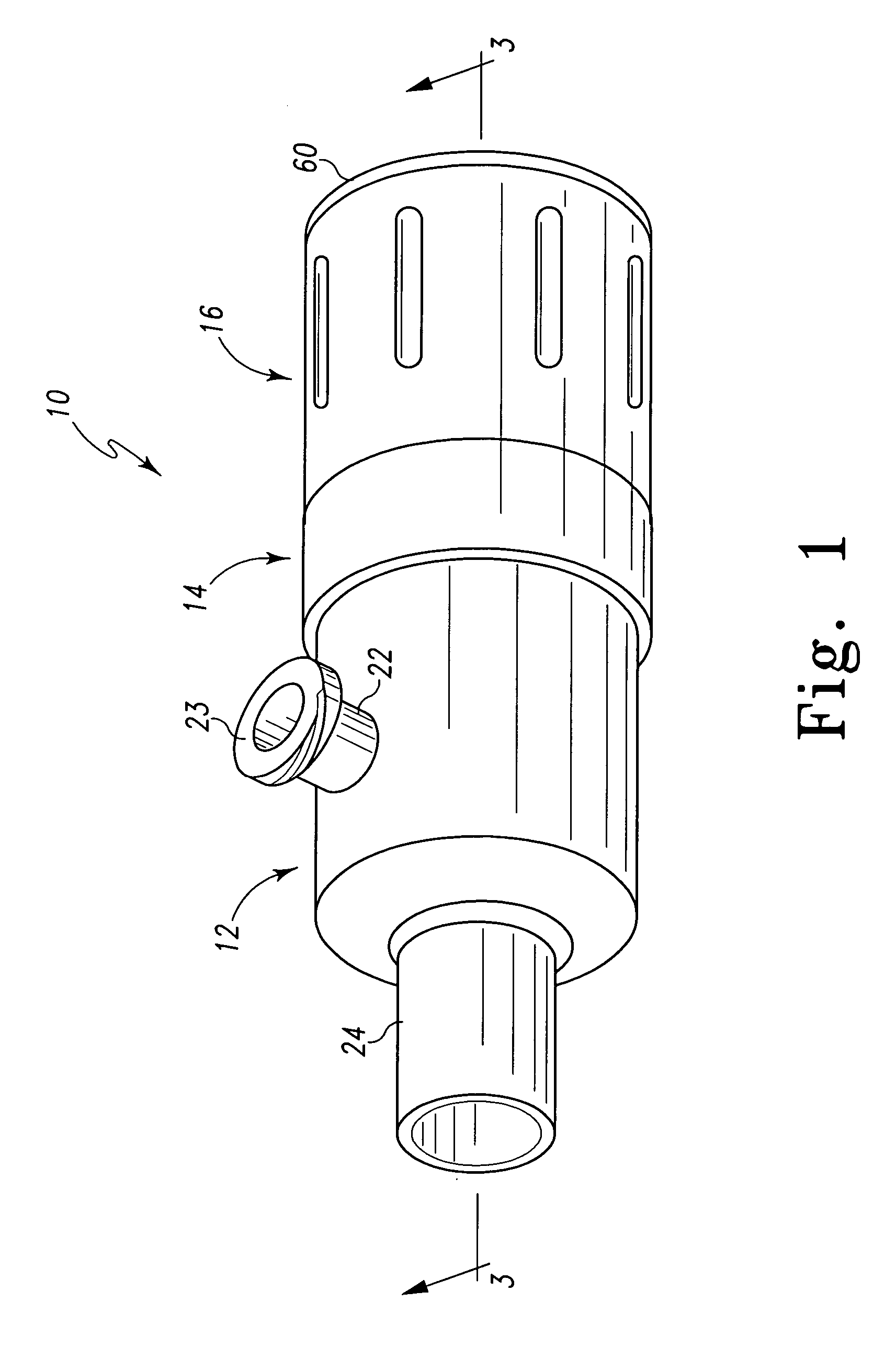
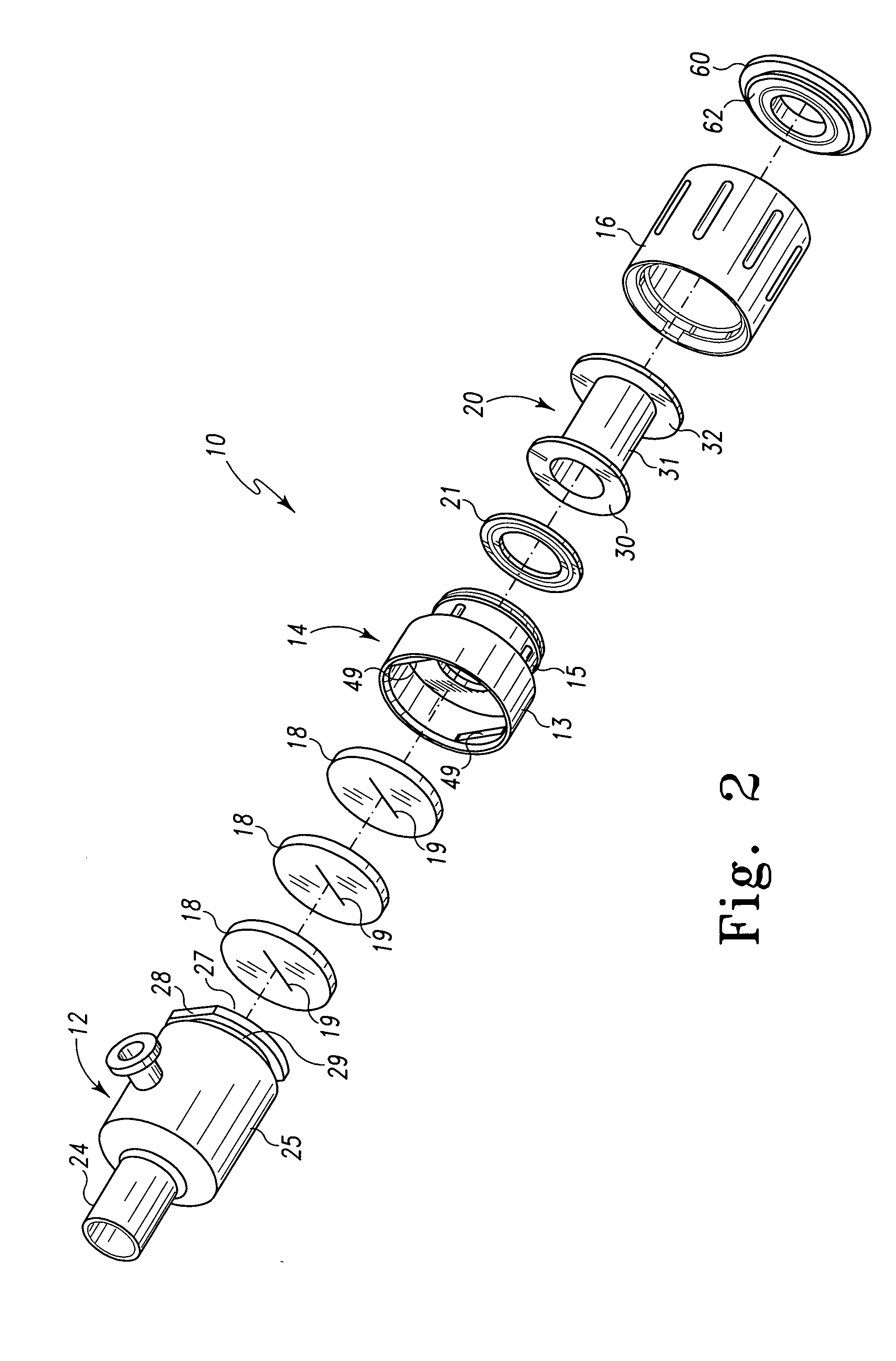
[0038] For the purposes of promoting an understanding of the principles of the invention, reference will now be made to the embodiments illustrated in the drawings, and specific language will be used to describe the same. It should nevertheless be understood that no limitation of the scope of the invention is thereby intended, such alterations and further modifications in the illustrated device, and such further applications of the principles of the invention as illustrated therein being contemplated as would normally occur to one skilled in the art to which the invention relates.

[0039] In the following discussion, the terms “proximal” and “distal” will be used to describe the opposing axial ends of the valve assembly, as well as the axial ends of various component features. The term “proximal” is used in its conventional sense to refer to the end of the assembly (or component thereof) that is closest to the operator during use of the assembly. The term “distal” is used in its conv...


PUM


Abstract

An iris-type valve assembly for controlling a flow of fluid. The assembly comprises a base member, a rotatable member, and an elongated elastomeric valve sheath. The distal end of the valve sheath is secured to the base member and the proximal end of the valve sheath is secured to the rotatable member. At least one of the valve sheath ends includes a flange that is secured to a valve-receiving surface of the base member or the rotatable member. The base member and the rotatable member are aligned to define an elongated passageway therethrough for passage of an interventional device, and the elastomeric valve sheath is disposed along the passageway and has a longitudinal opening therethrough for passage of the interventional device. Upon rotation of the rotatable member relative to the base member the longitudinal opening of the valve sheath is selectively constrictable to comprise a seal around the interventional device. The assembly may be provided with ratcheting members to inhibit recoil of the rotatable member, and rib members along the inner surface of the valve sheath to enhance the seal provided by the assembly.

Description

RELATED APPLICATIONS [0001] The present patent document claims the benefit of the filing date under 35 U.S.C. §119(e) of Provisional U.S. Patent Application Ser. No. 60 / 529,179, filed Dec. 11, 2003, and Provisional U.S. Patent Application Ser. No. 60 / 576,665, filed Jun. 3, 2004, which are hereby incorporated by reference.BACKGROUND [0002] 1. Technical Field [0003] The present application relates generally to medical devices, and more particularly, to a hemostatic valve assembly for controlling the flow of fluids through a medical device. [0004] 2. Background Information [0005] A variety of well-known medical procedures are performed by introducing an interventional device such as a catheter, trocar, sheath, stent and the like into a vessel in a patient's body. Typical procedures for introducing an interventional device into a blood vessel include the well-known Seldinger technique. The Seldinger technique involves opening a blood vessel with a needle, inserting a wire guide into the...

Claims


Application Information

Patent Timeline
Patent Type & Authority Applications(United States)
IPC IPC(8): A61B17/00A61B17/34A61M39/02A61M39/06
CPCA61B17/3462A61B17/3498A61B2017/00477A61M2039/0686A61M39/0613A61M2039/0633A61M2039/064A61M39/0208
Inventor HRUSKA, CHRISTOPHER L.DIXON, CHRISTOPHER G.BARR, AARONPAUL, RAM H. JR.ELLER, ALAN A.OSBORNE, THOMAS A.
Owner COOK MEDICAL TECH LLC
Why Eureka
Try Eureka