Cord retainer

a technology of retainer and cord, which is applied in the direction of flexible pipes, vehicles/pulleys, cables, etc., can solve the problems of electrical lead still in direct contact with metal surfaces, affecting the work efficiency of workers, and causing sagging of cords, etc., to achieve the effect of eliminating sagging

Inactive Publication Date: 2005-08-11
RYAN MARTIN RODNEY +2
View PDF5 Cites 10 Cited by
  • Summary
  • Abstract
  • Description
  • Claims
  • Application Information

AI Technical Summary

Benefits of technology

[0008] In accordance with one aspect of the present invention there is provided a cord retainer for suspending a cord above the ground or floor, the cord retainer including a body, a clamp means depending from the body and a mounting means in operative association with the body, the clamp means being able to clamp the cord and retain it against substantial longitudinal movement with respect to the cord retainer, and the clamp means including a resilient retarding means for allowing limited displacement of the cord in its longitudinal direction.
[0009] In accordance with another aspect of the present invention there is provided a cord retainer for suspending a cord above the ground or floor, the cord retainer including a body, a resilient web depending from the body and a mounting means in operative association with the body, the resilient web including at least one aperture provided with a slit extending to an outer edge of the resilient web, the slit being arranged so that the resilient web can be deformed for allowing insertion of the cord into the aperture via the slit and therein the cord is substantially retained against longitudinal movement with respect to the resilient web, and the mounting means enabling the body to be suspended above the ground or floor.
[0010] In the context of the present invention the cord is retained against substantially longitudinal movement with respect to the web to the extent that the cord in substantially inhibited from sliding in the hole in the web, under the force of its own weight or during normal installation of the cord, into two spaced apart cord retainers. That is, in the normal use of the cord retainer and under normal loads placed on the cord there is substantially no sliding of the cord through the hole. This allows the cord to be tensioned between adjacent cord retainers for tensioning the cord against the force of its own weight and thus substantially eliminates sagging of the cord between said cord retainers.

Problems solved by technology

In the building industry there have been numerous deaths by electrocution on building sites attributed to the placement of electrical leads on the ground or floor.
These leads may be accidentally severed or have water enter at their joins both of which can easily result in electrocution.
This has the problem that the electrical lead is still in direct contact with a metal surface (in the case of scaffolding).
Such suspension also is generally inconvenient for the tradesman because of the time taken to tie the electrical leads to the scaffolding.
Also, the tape and cable ties cannot be reused.
Further, these tying methods tend to result in damage to the electrical lead and significantly reduce the serviceable life of the electrical lead.
This has a number of problems.
Firstly, the leads must be secured to each stand otherwise they sag too much between adjacent stands.
Sometimes this is done by tying the lead about the stand—which tends to damage the lead and is dangerous.
Secondly, when a tradesman wishes to retrieve his lead he has to find it amongst many other similar or identical leads placed by other tradesmen, which is difficult and time consuming.
Still further, the stands tend to be somewhat unstable, particularly when supporting a number of leads and so the stands are prone to falling over when a tradesman attempts to remove his lead from the stand.
Still further, even though the leads are secured between adjacent stands there is still a significant sagging problem, which is a hazard in itself—requiring tradesmen to stoop under the leads to avoid knocking the stands over.
The sagging problem remains because the stands are moveable (that is, not fixed to the ground) and therefore incapable of allowing much tensioning of the leads between adjacent stands.
A problem with this device is that the clip is resilient only in a direction radially of the cord and has no resilience axially of the cord.
Accordingly, slippage of the cord in the clip is likely to happen.
Hence, two adjacent ones of the device of 716033 would not be capable of allowing for tensioning of the cords, and so sagging of the cords would still be a problem.

Method used


Image

  • Cord retainer
  • Cord retainer
  • Cord retainer

Examples


Embodiment Construction

)

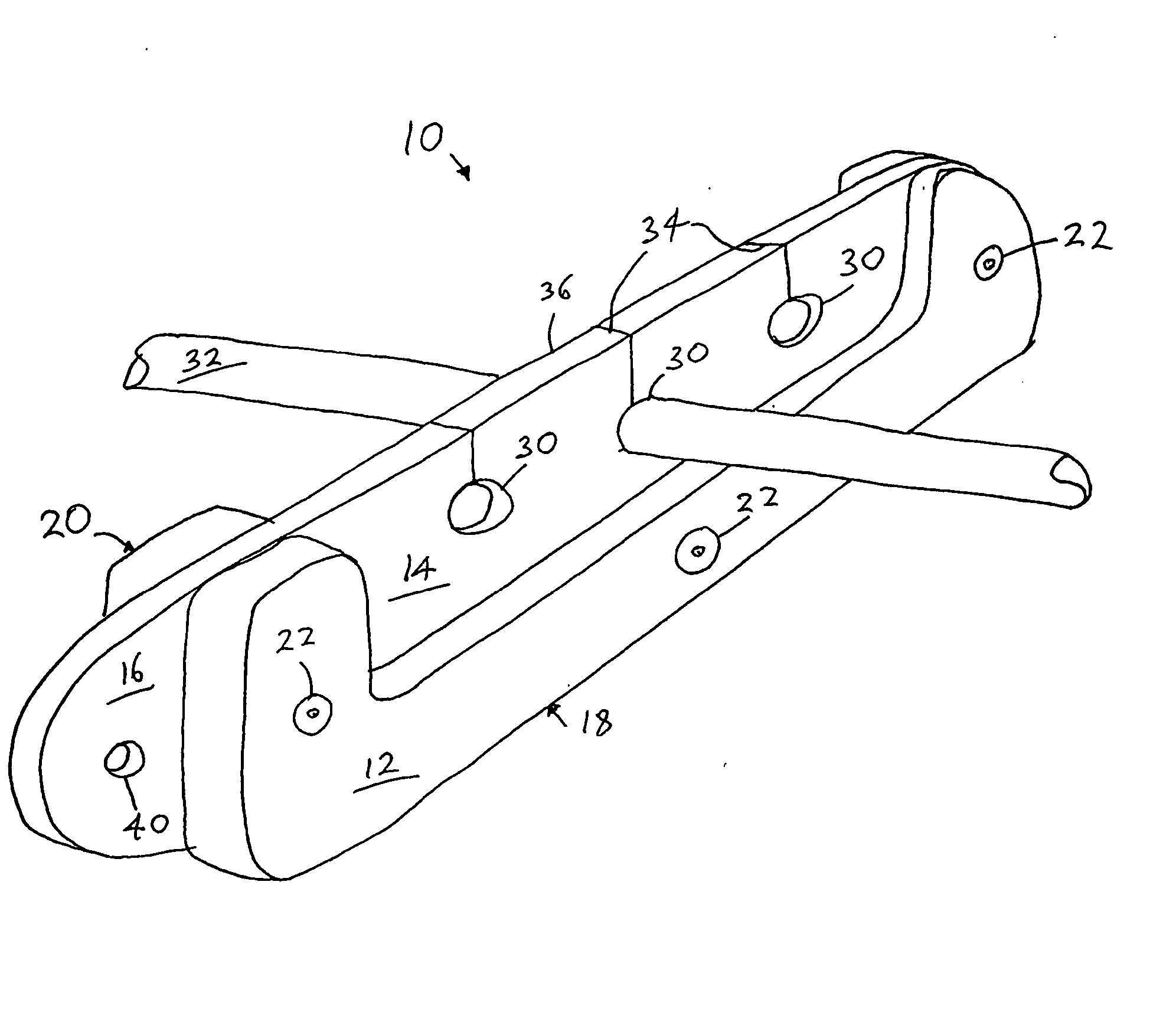
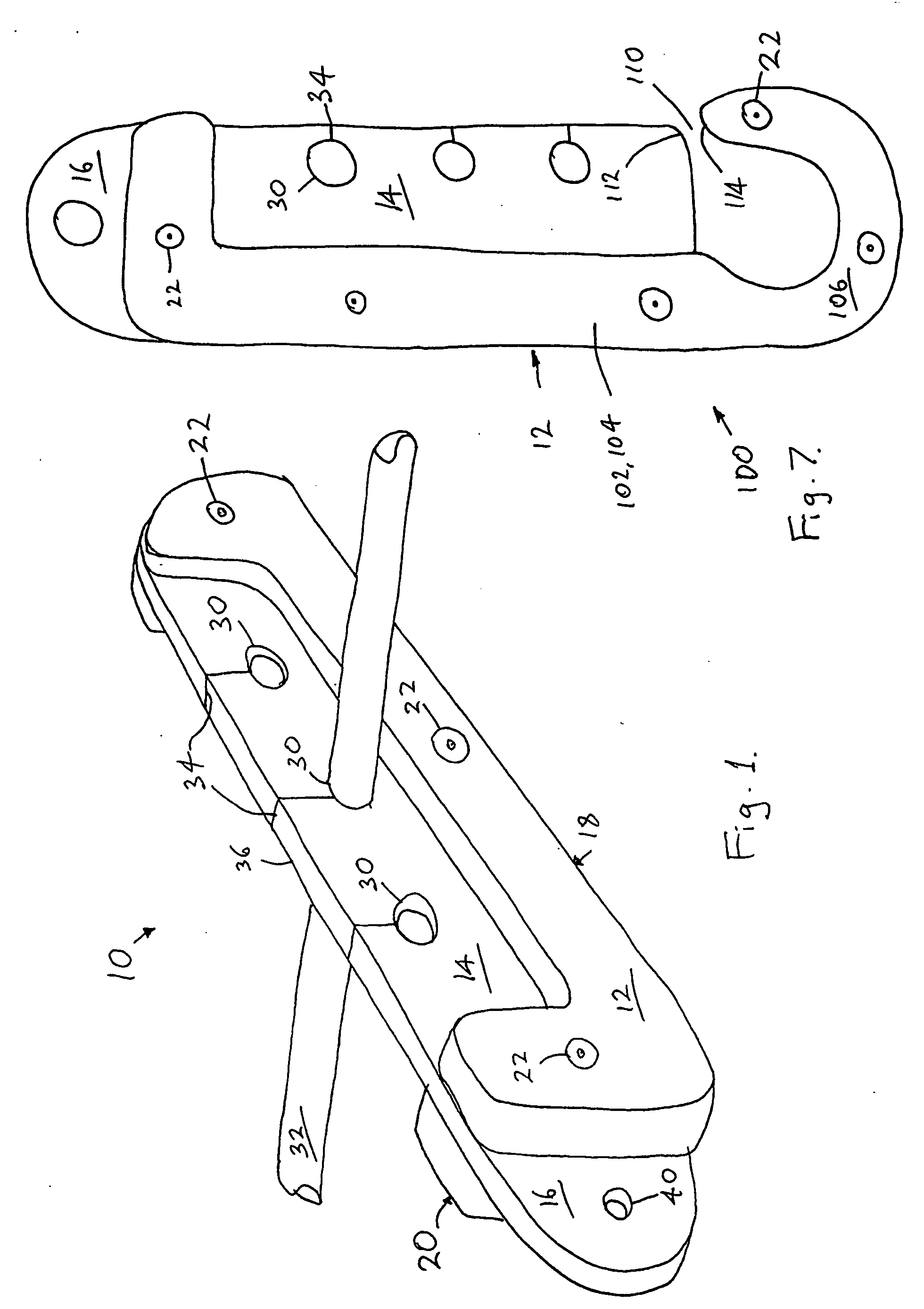
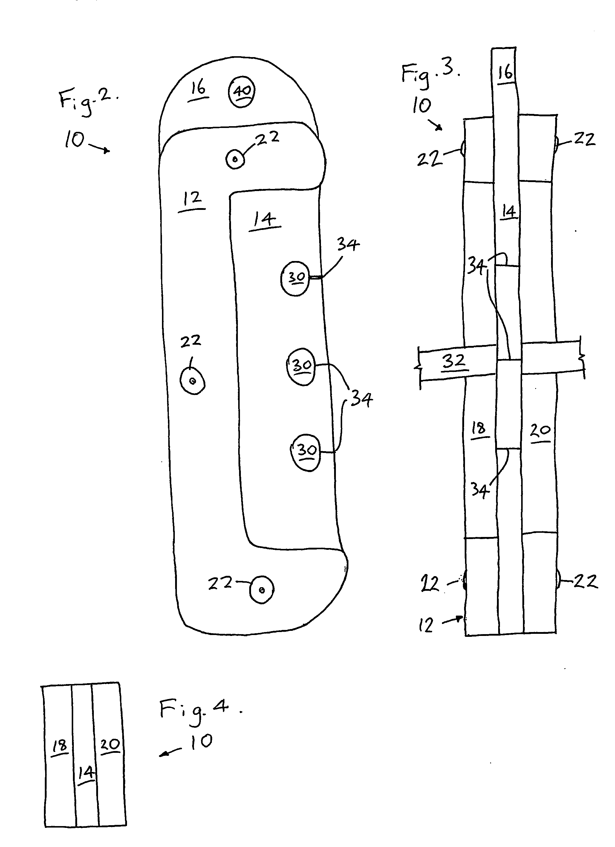
[0028] In FIGS. 1 to 4 there is shown an electrical lead retainer 10 in accordance with one aspect of the present invention. The electrical lead retainer 10 includes a body 12, a resilient web 14 depending from the body and a mounting means in the form of a mounting tab 16 in operative association with the body 12.

[0029] The body 12, in the exemplary embodiment, is substantially C-shaped when viewed in plan, substantially flat along its length and of substantially uniform depth. The body is conveniently formed of two halves 18 and 20 both having the aforementioned shape. The two halves 18 and 20 sandwich the web 14 between them and have holes that receive rivets 22, or the like fixings, to fix the two halves 18 and 20 about the web 14. A workable length for the two halves 18 and 20 is about 160 mm, a width of about 50 mm and a thickness of about 10 mm. These dimensions are only to be taken as a guide as to what can work for a conventional 240-volt mains electrical lead having a di...


PUM


Abstract

A cord retainer (10, 100, 140, 160) for retaining cords such as electrical power leads (32) and pneumatic hoses in an elevated position above the ground or floor. The cord retainer (10, 100, 140, 160) has a flexible web (14, 146, 168) with holes (30, 148) dimensioned to receive a cord (32) and substantially retained it against longitudinal movement with respect to the web (14, 146, 168) to the extent that the cord (32) is substantially prevented from sliding longitudinally in the hole (30, 148) under the force of its own weight or during normal installation of the cord (32), in two spaced apart cord retainers (10, 100, 140, 160). A series of frames 170, 180 and 190 are also provided for attaching the cord retainer (10, 100, 140, 160) structures on building and construction sites.

Description

FIELD OF THE INVENTION [0001] The present invention relates to a cord retainer for retaining cords in an elevated position above the ground or floor. More particularly the present invention relates to an electrical lead retainer for suspending electrical leads above the ground to reduce the risk of electrical shock and electrocution. Typically, such electrical leads include mains power leads and welding power leads. [0002] Hereinafter the present invention will be described with particular reference to cords being electrical leads although it is to be understood that it could be used with other cords, including pneumatic leads such as, for example, as used in oxy-acetylene welding. Also, hereinafter the term “lead” will generally be used as an abbreviation of the term “electrical lead”. BACKGROUND OF THE INVENTION [0003] In the building industry there have been numerous deaths by electrocution on building sites attributed to the placement of electrical leads on the ground or floor. ...

Claims


Application Information

Patent Timeline
Patent Type & Authority Applications(United States)
IPC IPC(8): F16B1/00F16B2/10F16B2/22F16L3/01F16L3/08F16L3/22H02G3/30H02G3/32
CPCH02G3/24Y10T24/39H02G3/32
Inventor RYAN, MARTIN RODNEYMONTGOMERY, MICHAEL JOHNCALLAGHAN, PAUL DAMIAN
Owner RYAN MARTIN RODNEY
Why Eureka
Try Eureka