Vertically oriented jerky dehydrator

a vertical orientation, jerky dehydrator technology, applied in the direction of meat/fish preservation by drying, milk preservation, food shaping, etc., can solve the problems of difficulty in evenly drying the contents of the rack, difficulty in circulating air through the rack, and the disadvantages of electric powered dehydrators. , to achieve the effect of minimizing the cleaning time and successful operation of the dehydration process

Inactive Publication Date: 2005-08-11
LAMASTER ALAN L +1
View PDF27 Cites 12 Cited by
  • Summary
  • Abstract
  • Description
  • Claims
  • Application Information

AI Technical Summary

Benefits of technology

[0014] The receptacles on each basket are slipped over mating pins on the racking gird, so that the baskets are aligned, parallel to each other, and vertically oriented. The racking grid, with the baskets secured thereto, is placed into an upwardly opening tray, and the loaded tray is introduced into an oven to dry the jerky. Heated air circulates evenly about the baskets and uniformly dries the contents thereof; the drippings are collected in the tray, so that clean-up time is minimized.
[0015] In a preferred embodiment, which finds particular application when a meat product is intended to be sliced, after cooking, into strips, the jerky is formed into a patty prior to introduction into each rack. The method of forming the patty is unique, for a generally rectangular open form receives a charge of jerky, the dimensions of the patty are chosen to fit neatly within each basket, and contribute to the successful operation of the dehydration process.

Problems solved by technology

However, the electrically powered dehydrators possessed certain disadvantages and operating deficiencies.
For example, known dehydrators are bulky and consume significant space, both on a counter top, when in use, or in a storage area, when not in use.
Known dehydrators employ several horizontally disposed racks to receive the meat jerky, and difficulty is encountered in circulating air through the racks to evenly dry the contents of the racks.
Blowers, vents, and louvers, are required in an effort to provide a degree of uniformity to the heated air to be circulated, and known dehydrators are thus relatively costly to purchase, operate and maintain.
Also, the fat content in the jerky retained on the upper racks drips down onto the lower racks, thus diminishing the quality, and taste, of the product on the lower racks.

Method used


Image

  • Vertically oriented jerky dehydrator
  • Vertically oriented jerky dehydrator
  • Vertically oriented jerky dehydrator

Examples


Embodiment Construction

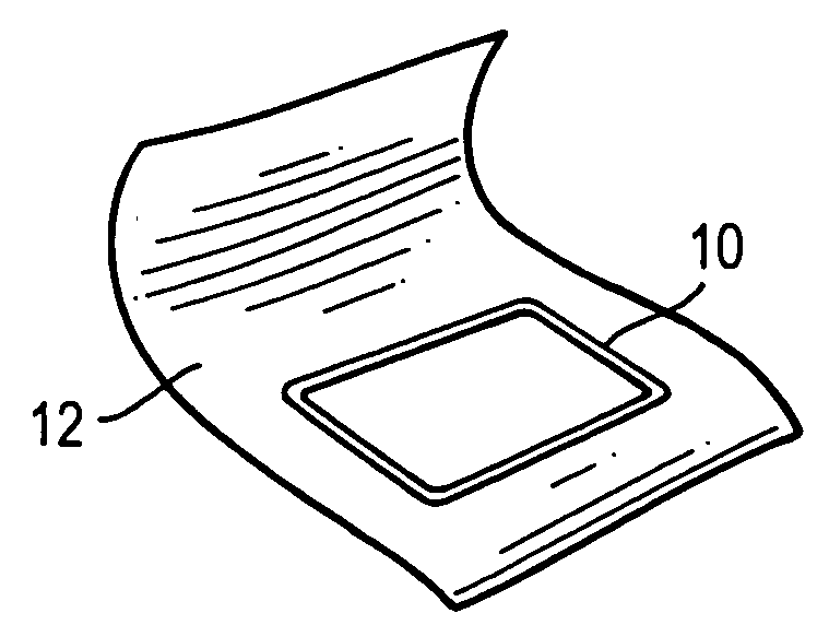
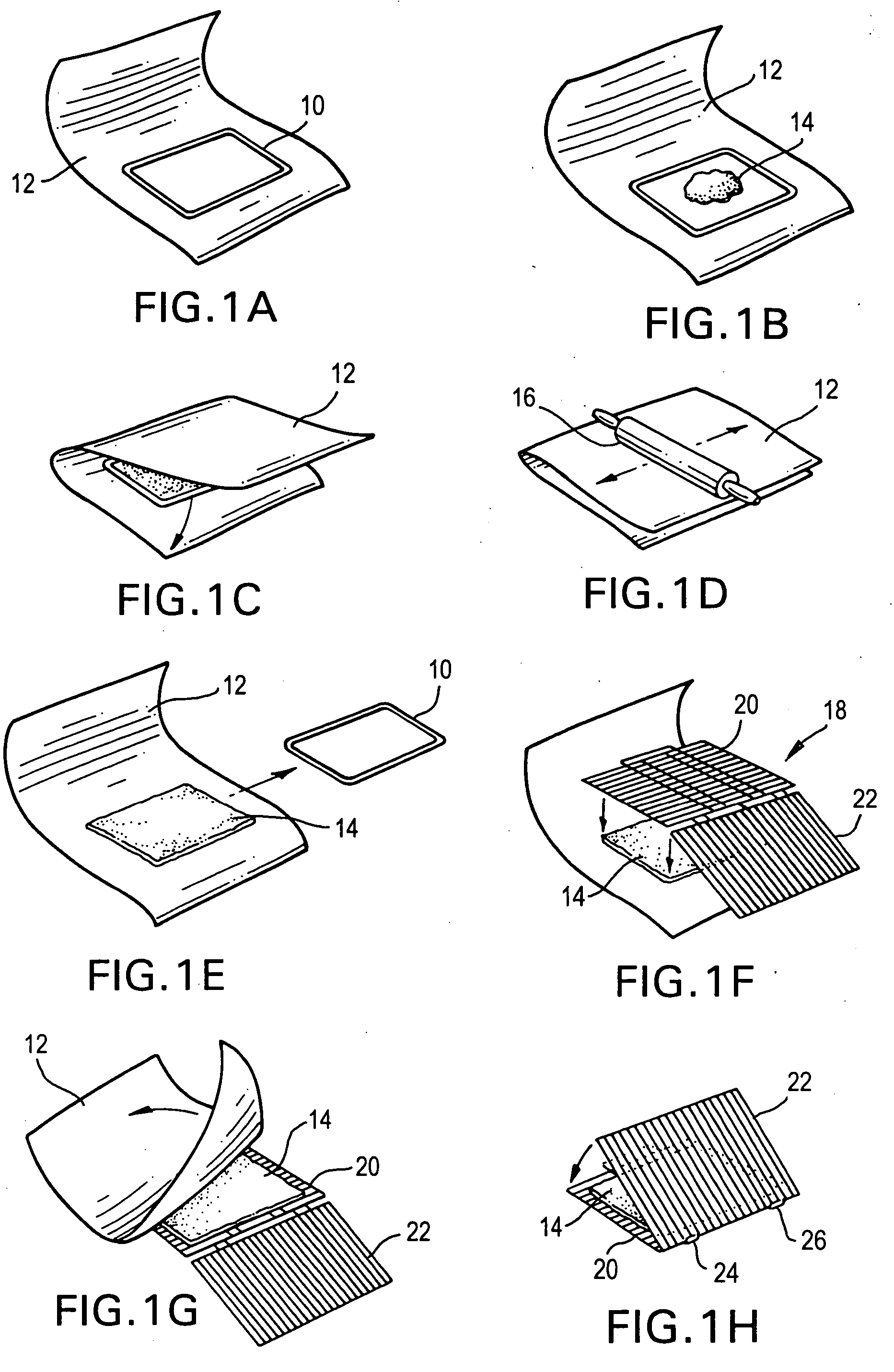
[0025]FIGS. 1A-1H depict, in schematic fashion, the sequence of steps used to prepare ground jerky for introduction into the dehydrator constructed in accordance with the principles of the instant invention. FIG. 1A shows form 10, of rectangular shape, placed on top of a sheet of non-stick paper 12. The non-stick paper may be parchment, wax paper, or aluminum foil, and the sheet of non-stick paper may be twenty four inches in length. Form 10 is positioned to leave a buffer, or margin, of two inches on each side and at the end of the paper.

[0026] A scoop, or handful, of ground jerky 14 is placed within form 10, as shown in FIG. 1B. The scoop may contain three-quarters of a pound of jerky, seasoned according to the user's recipes. The upper end of paper 12 is then folded over the top of form 10, so that the edges of the upper and lower runs of paper 12 are in alignment, as shown in FIG. 1C. Rolling pin 16 is then rolled back and forth across the upper surface of folded over paper 12,...


PUM


Abstract

A jerky dehydrator comprises several baskets for receiving and retaining the product to be dehydrated and a racking grid for retaining several baskets in a vertical orientation. The racking grid is inserted into a metal tray, and the tray is inserted into the oven of a household range. The oven is preheated, prior to inserting the tray and its contents. Subsequently, the oven is maintained at a low temperature, about 200°, and the door of the oven is held open, slightly, to allow moisture to escape. Each basket comprises a first grate and a second grate, retained in pivotal relation by a pair of hinge clips. Tension springs, secured to an anchor on one grate and an extension on the other grate, urge the grates togther to form a basket and retain the jerky therebetween during the dehydration process. Receptacles at the trailing edge of one grate slip over upstanding pins on the racking grid and lock each basket in its vertical orientation. A form may be used to mold the jerky into a patty or square, of desired dimensions, prior to inserting same into the basket.

Description

BACKGROUND OF THE INVENTION [0001] The preservation of food by dehydration has long been recognized. The earliest efforts at dehydration involved placing the food product, in an open container, for exposure to the sun and ambient conditions. [0002] In more recent years, food dehydrators, with motor driven fans or blowers to force heated air through a cabinet or housing, and multiple shelves to receive the product to be dehydrated, have been developed for home use. A few of the many dehydrators developed for home use are discussed below. [0003] To illustrate, U.S. Pat. No. 3,943,842, Bills et al, discloses a cabinet dehydrator (10) for long term preservation of food under close control of time, temperature, and humidity. Blower (32) obtains intake air from the surrounding atmosphere and forces same into the interior of the cabinet. As shown by the directional arrows in FIG. 1, the air passes over heater coil (50), through port (66) into the interior of the cabinet, and then circulate...

Claims


Application Information

Patent Timeline
Patent Type & Authority Applications(United States)
IPC IPC(8): A23B4/03A23C15/04
CPCA23B4/031
Inventor LAMASTER, ALAN L.WISDO, JOHN E.
Owner LAMASTER ALAN L
Why Eureka
Try Eureka