Fuel vapor treatment device

a technology of fuel vapor treatment and treatment device, which is applied in the direction of combustion air/fuel air treatment, machine/engine, separation process, etc., can solve the problems of unavoidably increasing the production cost of the fuel vapor treatment device, further lowering the emission amount of fuel vapor to atmospheric air, and overcoming the drawbacks

Active Publication Date: 2005-08-11
MAHLE JAPAN LTD
View PDF8 Cites 31 Cited by
  • Summary
  • Abstract
  • Description
  • Claims
  • Application Information

AI Technical Summary

Benefits of technology

[0007] It is, therefore, an object of the present invention to provide an improved fuel vapor treatment device which can effectively overcome drawbacks encountered in conventional fuel vapor treatment devices.
[0008] Another object of the present invention is to provide an improved fuel vapor treatment device which can effectively achieve both a sufficient reduction of emission of fuel vapor to atmospheric air and a high production efficiency for the fuel vapor treatment device.
[0009] A further object of the present invention is to provide an improved fuel vapor treatment device whose L / D value can be easily changed without making a design change of the whole body of a casing of the fuel vapor treatment device.

Problems solved by technology

However, in the recent years, a regulation for emission control of fuel vapor to atmospheric air has become more strict, and therefore it has been required to further lower the emission amount of fuel vapor to atmospheric air.
In the above conventional fuel vapor treatment device, increasing the L / D value is taken into consideration; however, in order to sufficiently increase the L / D value, a new design for the whole casing of the fuel vapor treatment device is necessary thereby unavoidably increasing a production cost of the fuel vapor treatment device.
To meet this requirement, it is necessary to prepare a plurality of production equipments for separately produce a plurality of different casings, thereby providing the fear of lowering the production efficiency of the fuel vapor treatment devices.

Method used


Image

  • Fuel vapor treatment device
  • Fuel vapor treatment device
  • Fuel vapor treatment device

Examples


first embodiment

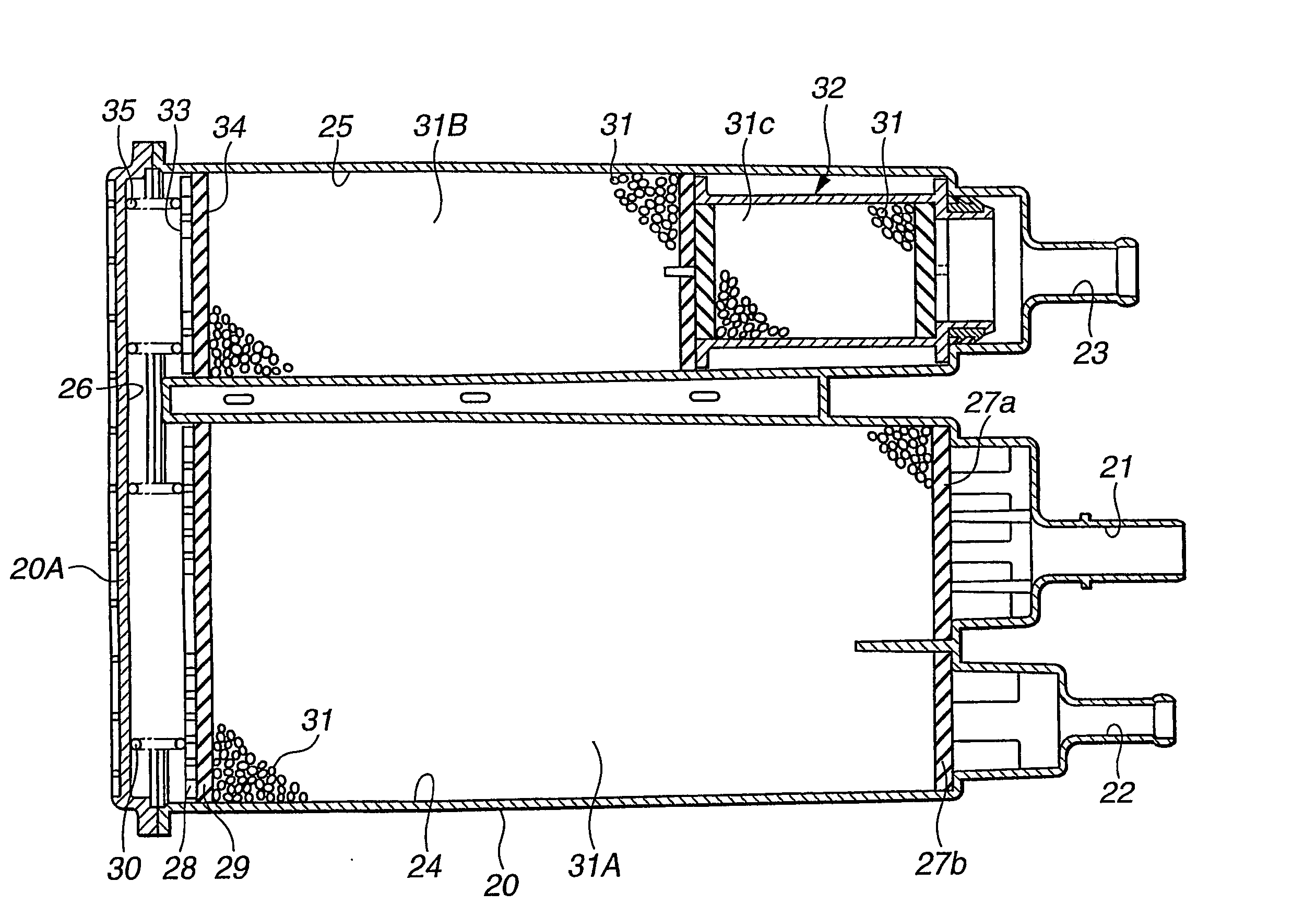
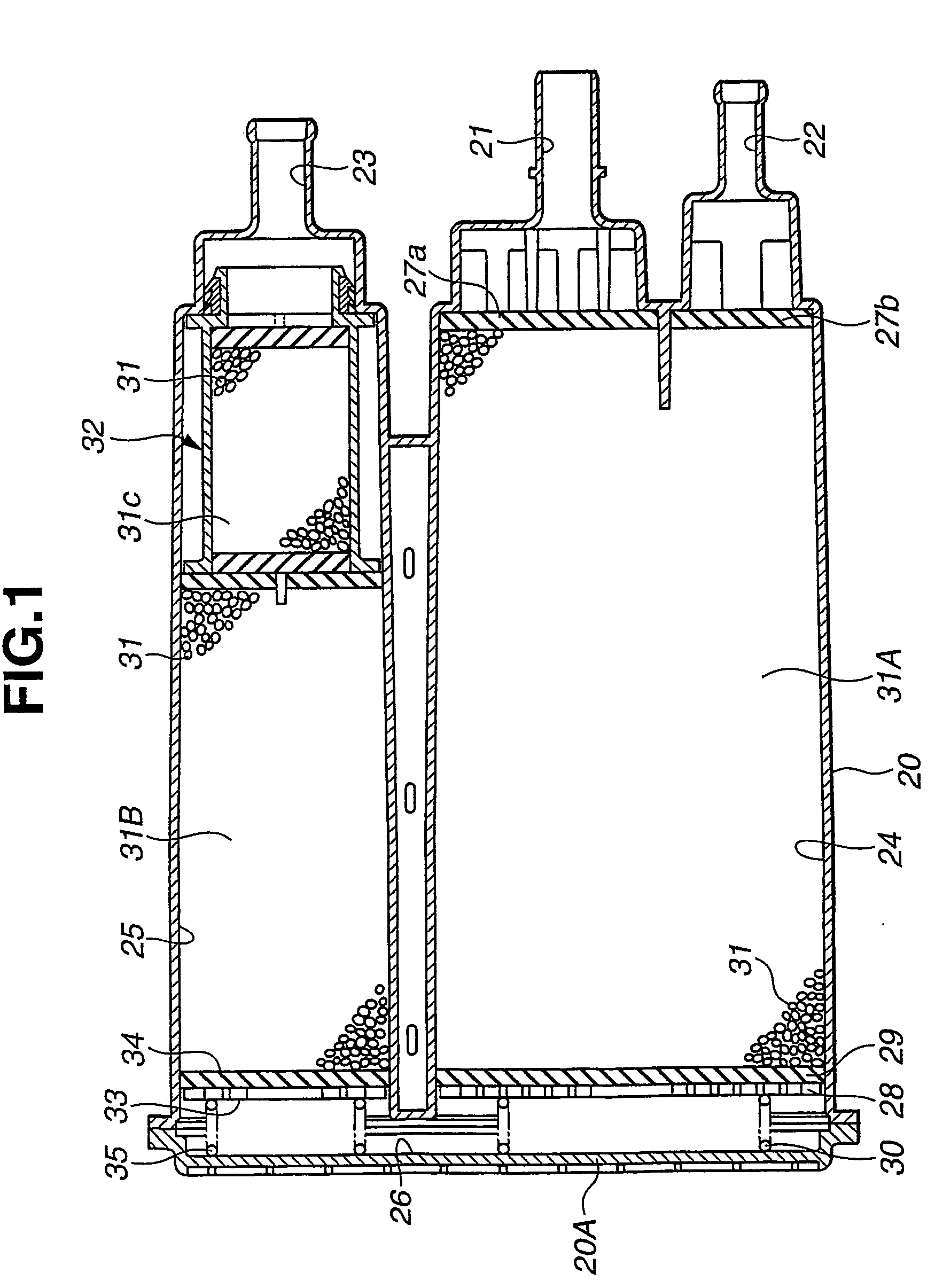
[0033] Referring now to FIGS. 1 to 3, a fuel vapor treatment device according to the present invention is illustrated. The vapor treatment device comprises a casing 20 formed of a resin material (synthetic resin). The casing 20 is formed at its one end side with a charge port 21, a purge port 22 and an atmospheric air port 23. The charge port 21 is connected to a fuel tank (not shown) of an automotive vehicle. The purge port 22 is connected to an intake side or system (not shown) of an internal combustion engine (not shown) of the vehicle. The atmospheric air port 23 is communicated with atmospheric air. The inside of the casing 20 is divided into a first charging chamber 24 and a second charging chamber 25. In other words, the casing 20 includes a first casing section (no numeral) defining therein the first charging chamber 24, and a second casing section (no numeral) defining therein the second charging chamber 25. The first charging chamber 24 is communicated with the charge port...

fifth embodiment

[0078] With the thus arranged fuel vapor treatment device of the fifth embodiment, HC gas reaching the second activated carbon layer 31B during stop of the engine and the like flows meandering through the space 178 located around the base section of the air guide member 174 and through the bent gas flow passage 175 so as to reach the tip end side of the cylindrical wall section 95. Then, HC gas flows into the adsorbing material formed body 90 through the tip end of the cylindrical wall section 95 so as to be adsorbed into the adsorbing material formed body 90.

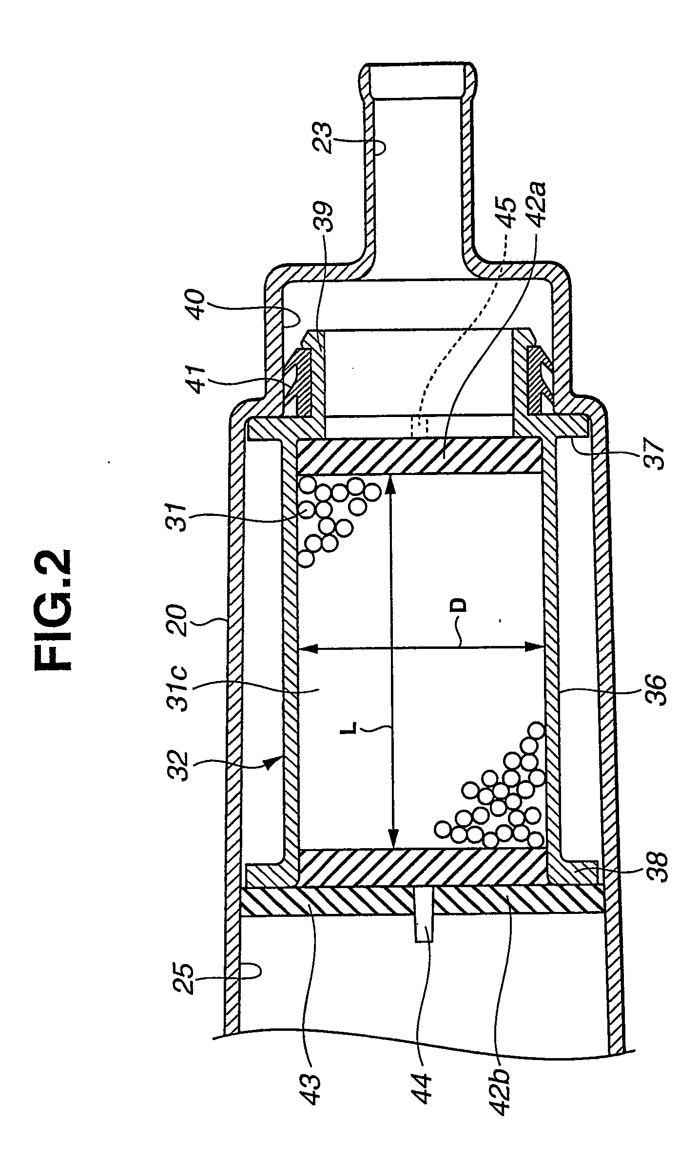
[0079] In this embodiment, the adsorbing material formed body 90 has the cross-sectional area smaller than the cross-sectional area of the second charging chamber 25, and the L / D value of the adsorbing material formed body 90 is set at about 1.5 (not less than 1) so that the L / D value of the whole fuel vapor treatment device becomes larger than about 1.5. Additionally, the second activated carbon layer 31B and the adsorbing mat...

third embodiment

[0088] Also in this embodiment, like the other embodiments, the air guide member 174 may be formed integral with the second casing section of the casing 20, and a cylindrical wall section and an atmospheric air port section formed with the atmospheric air port may be formed-separate from the casing 20, the cylindrical wall section being disposed inside the second casing section of the casing 20. In this case, the fuel adsorbing material such as activated carbon is disposed in the cylindrical wall section thereby forming the adsorbing material cartridge. Although the casing 20 has been shown and described as having the generally U-shaped gas flow passage, the shape of the casing 20 may be straight like that in FIG. 6 in which the straight casing 20 is formed with the charge and purge ports 21, 22 at its axial one end and with the atmospheric air port at its axial other end, forming a straight air flow passage extending from the axial one end to the axial other end of the casing 20.

[0...


PUM


Abstract

A fuel vapor treatment device for suppressing emission of fuel vapor from a fuel tank or the like of an automotive vehicle. The fuel vapor treatment device comprises a casing having a charge port connected to a fuel tank, a purge port connected to an intake section of an engine, and an atmospheric air port through which atmospheric air is introduced. Fuel vapor adsorbing material is filled in the casing. Additionally, an adsorbing material cartridge is disposed in a part of the casing and includes a cylindrical cartridge main body section having a cross-sectional area smaller than that of the casing. Fuel vapor adsorbing material is filled in the cartridge main body section. Air introduced from the atmospheric air port is flowable through the inside of the cartridge main body section to the fuel vapor adsorbing material in the casing.

Description

TECHNICAL FIELD [0001] This invention relates to improvements in a fuel vapor treatment device configured to adsorb fuel vapor from a fuel tank and the like of an automotive vehicle and release the adsorbed fuel to be combusted in an engine during operation of the engine. BACKGROUND ART [0002] The fuel vapor treatment device of this type is disclosed in Japanese Patent Provisional Publication No. 2002-30998 and will be discussed with reference to FIG. 18. The fuel vapor treatment device includes a casing 1 which has a charge port 3 connected to a fuel tank 2, a purge port 3 connected to an intake manifold 5 of an engine 4, and an atmospheric air port communicated with atmospheric air. During stopping of the engine, gas containing fuel vapor (fuel component) is introduced from the charge port 3 into the casing. Fuel vapor adsorbing material 8 such as activated carbon is filled in the casing 1 so as to adsorb or remove fuel vapor in the gas. The gas from which fuel vapor has been remo...

Claims


Application Information

Patent Timeline
Patent Type & Authority Applications(United States)
IPC IPC(8): F02M25/08
CPCF02M25/0854
Inventor UCHINO, MASASHINAKANO, MASARUYAMADA, EIJIYOSHIDA, HIROYUKIOKADA, HIROAKI
Owner MAHLE JAPAN LTD
Why Eureka
Try Eureka