Thermoelectric generator for internal combustion engine

a technology for internal combustion engines and generators, applied in the direction of generators/motors, thermoelectric devices, transportation and packaging, etc., can solve problems such as inflicting damage on thermoelectric generation elements, and achieve the effect of reducing the possibility of damage to thermoelectric generation elements

Inactive Publication Date: 2005-08-11
TOYOTA JIDOSHA KK
View PDF8 Cites 87 Cited by
  • Summary
  • Abstract
  • Description
  • Claims
  • Application Information

AI Technical Summary

Benefits of technology

[0007] It is an object of the present invention to provide a thermoelectric generator for an internal combustion chamber that reduces the possibility of a thermoelectric generation element being damaged.

Problems solved by technology

This may inflict damage on the thermoelectric generation element.

Method used


Image

  • Thermoelectric generator for internal combustion engine
  • Thermoelectric generator for internal combustion engine
  • Thermoelectric generator for internal combustion engine

Examples


Embodiment Construction

[0020] In the drawings, like numerals are used for like elements throughout.

[0021] A thermoelectric generator 20 according to a preferred embodiment of the present invention will now be discussed with reference to FIGS. 2 to 5.

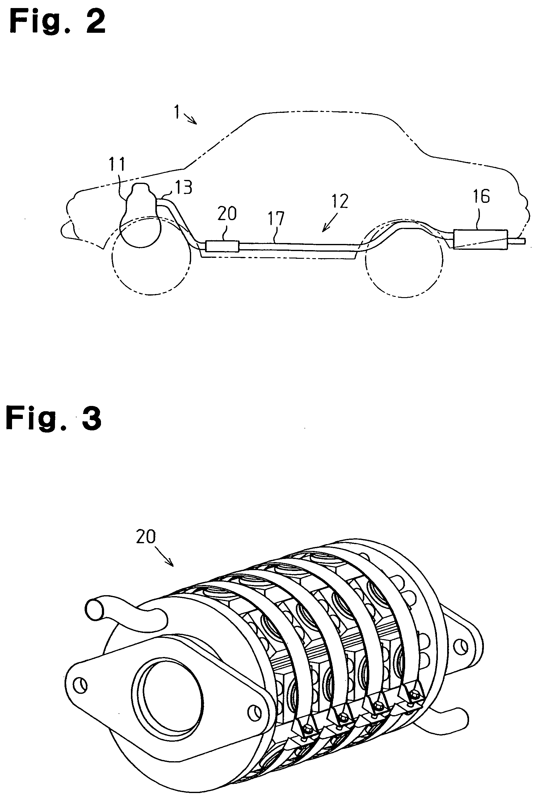
[0022]FIG. 2 schematically shows an exhaust system 12 of a vehicle 1 incorporating the thermoelectric generator 20.

[0023] As shown in FIG. 2, the exhaust system 12 includes an exhaust passage 17. From the upstream side with respect to the flow of exhaust, the exhaust passage 17 includes an exhaust manifold 13, the thermoelectric generator 20, and a muffler 16. In the exhaust system 12, exhaust emitted from an internal combustion engine 11 passes through the exhaust manifold 13, the thermoelectric generator 20, and the muffler 16 to be discharged into the atmosphere.

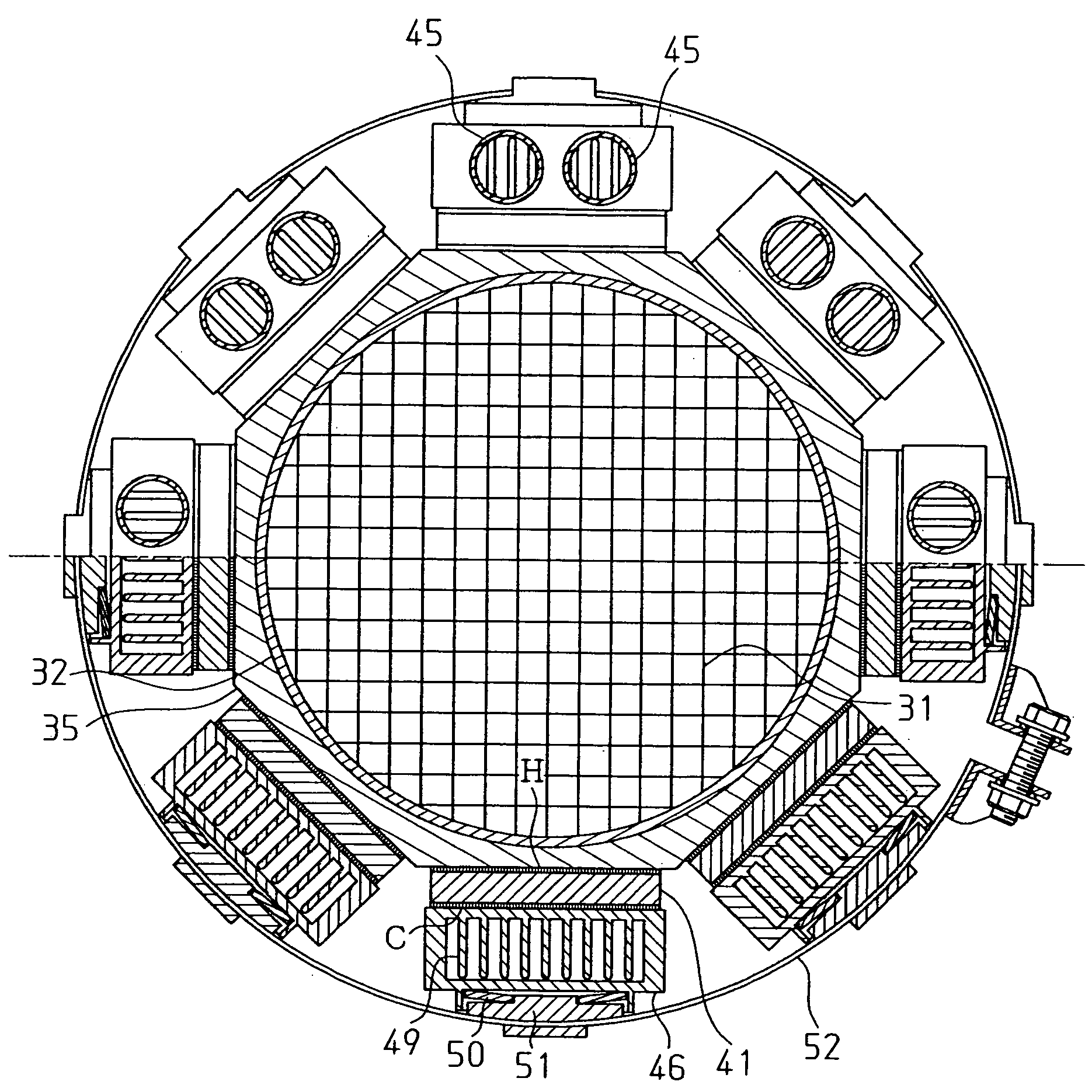
[0024] The thermoelectric generator 20 will now be discussed with reference to FIGS. 3 to 5.

[0025]FIG. 3 is a perspective view showing the thermoelectric generator 20. FIG. 4 is a partial cross...


PUM


Abstract

A thermoelectric generator for an internal combustion engine that prevents a thermoelectric generation element from being damaged. The thermoelectric generator includes a casing, which is arranged in an exhaust passage, and a sleeve. A cooling mechanism is arranged outside the sleeve. Thermoelectric generation elements are arranged between the sleeve and the cooling mechanism in a manner movable relative to both the sleeve and the,cooling mechanism. The thermoelectric generation elements convert heat energy from exhaust in the exhaust passage to electric energy.

Description

BACKGROUND OF THE INVENTION [0001] The present invention relates to a thermoelectric generator, and more particularly, to a thermoelectric generator for converting thermal energy of exhaust from an internal combustion engine to electric energy. [0002] The generation of electric power using a thermoelectric generation element, which converts thermal energy to electric energy, is known in the prior art. The thermoelectric generation element makes use of the Seeback effect in which the temperature difference between two ends (high temperature portion and low temperature portion) of a metal or semiconductor piece generates a potential difference between the high temperature and low temperature portions of the metal or semiconductor piece. A larger temperature difference increases the electric power generated by the thermoelectric generation element. [0003]FIG. 1 shows an example of the structure of a thermoelectric generation element. As shown in FIG. 1, the thermoelectric generation el...

Claims


Application Information

Patent Timeline
Patent Type & Authority Applications(United States)
IPC IPC(8): B60R16/02H01L35/28B60K13/04H01L35/30H01L35/32H02N10/00H02N11/00
CPCH01L35/30H10N10/13
Inventor SHIMOJI, KOUJISUZUKI, KOUICHIMATSUBARA, SHINYA
Owner TOYOTA JIDOSHA KK
Why Eureka
Try Eureka