Sanitary yard hydrant

a sanitary yard and water hydrant technology, applied in the field of water hydrants, can solve the problems of water in the hydrant to freeze, water in the riser to freeze to either clog or damage the hydrant, and achieve the effect of preventing the freezing of water in the riser

Active Publication Date: 2005-08-11
MURDOCK INC
View PDF7 Cites 4 Cited by
  • Summary
  • Abstract
  • Description
  • Claims
  • Application Information

AI Technical Summary

Benefits of technology

[0008] In another aspect of the invention, the hydrant further includes a chamber housing, located at a distal end of the housing beneath the frost line. The chamber housing defines a chamber into which residual water remaining in the riser after flow of water has been shut off may be drawn to empty the riser and thereby prevent freezi

Problems solved by technology

Furthermore, because these outdoor hydrants may be exposed to freezing temperatures, there is a potential for water in the hydrant to become frozen, where it may clog or damage the hydrant.
For example, the external riser which connects the valve buried beneath the frost line to the outlet above the surface of the ground may be exposed to freezing temperatures, whereby water in the riser can freeze to either clog or damage the hydrant.
This solution creates further problems, however.
If the residual water from the riser is drained into the soil around the hydrant, a potential is created for “brown water” to enter the hydrant through drain holes, whereby fresh water may become contaminated on next use of the hydrant.
Because

Method used


Image

  • Sanitary yard hydrant
  • Sanitary yard hydrant
  • Sanitary yard hydrant

Examples


Embodiment Construction

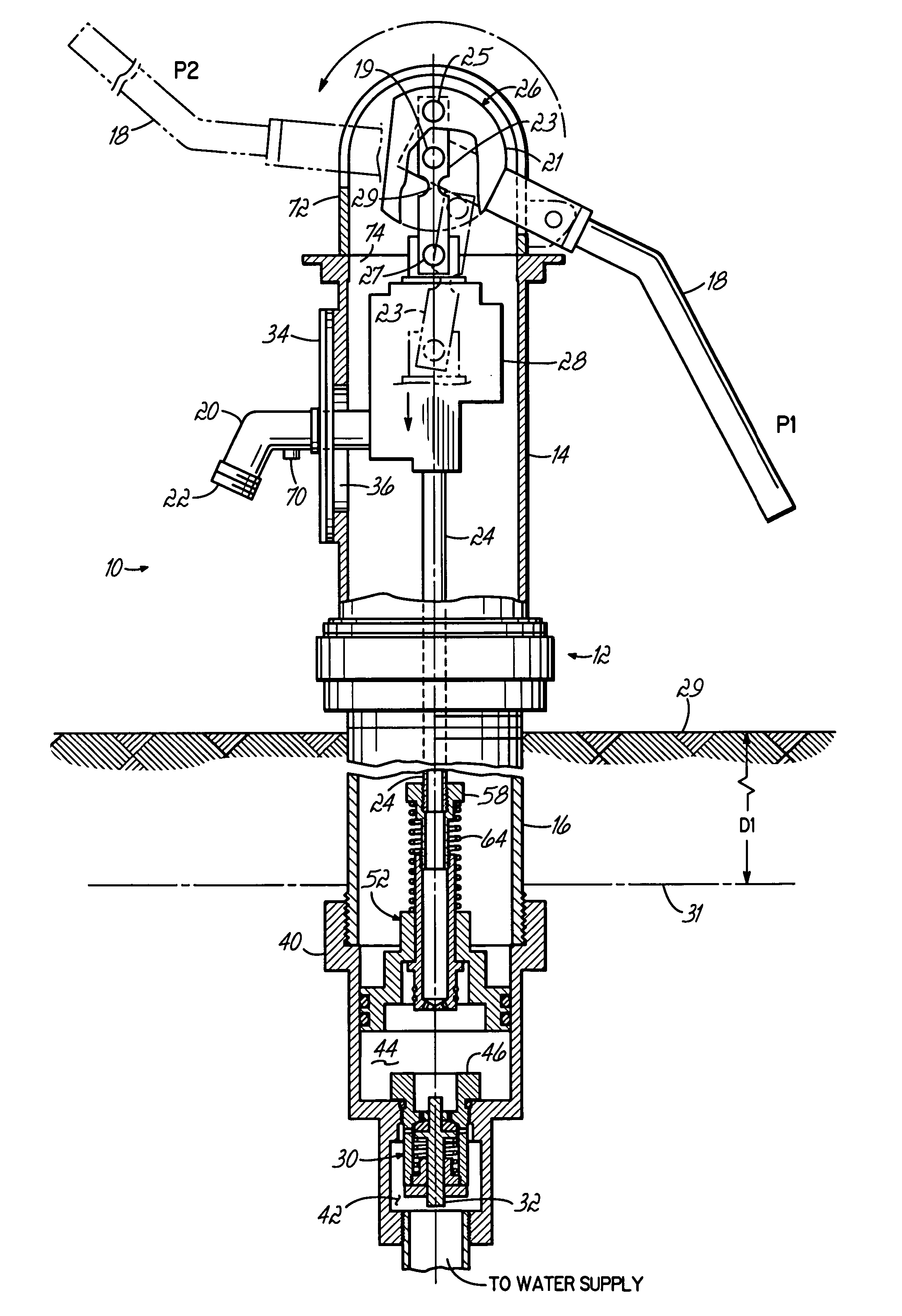
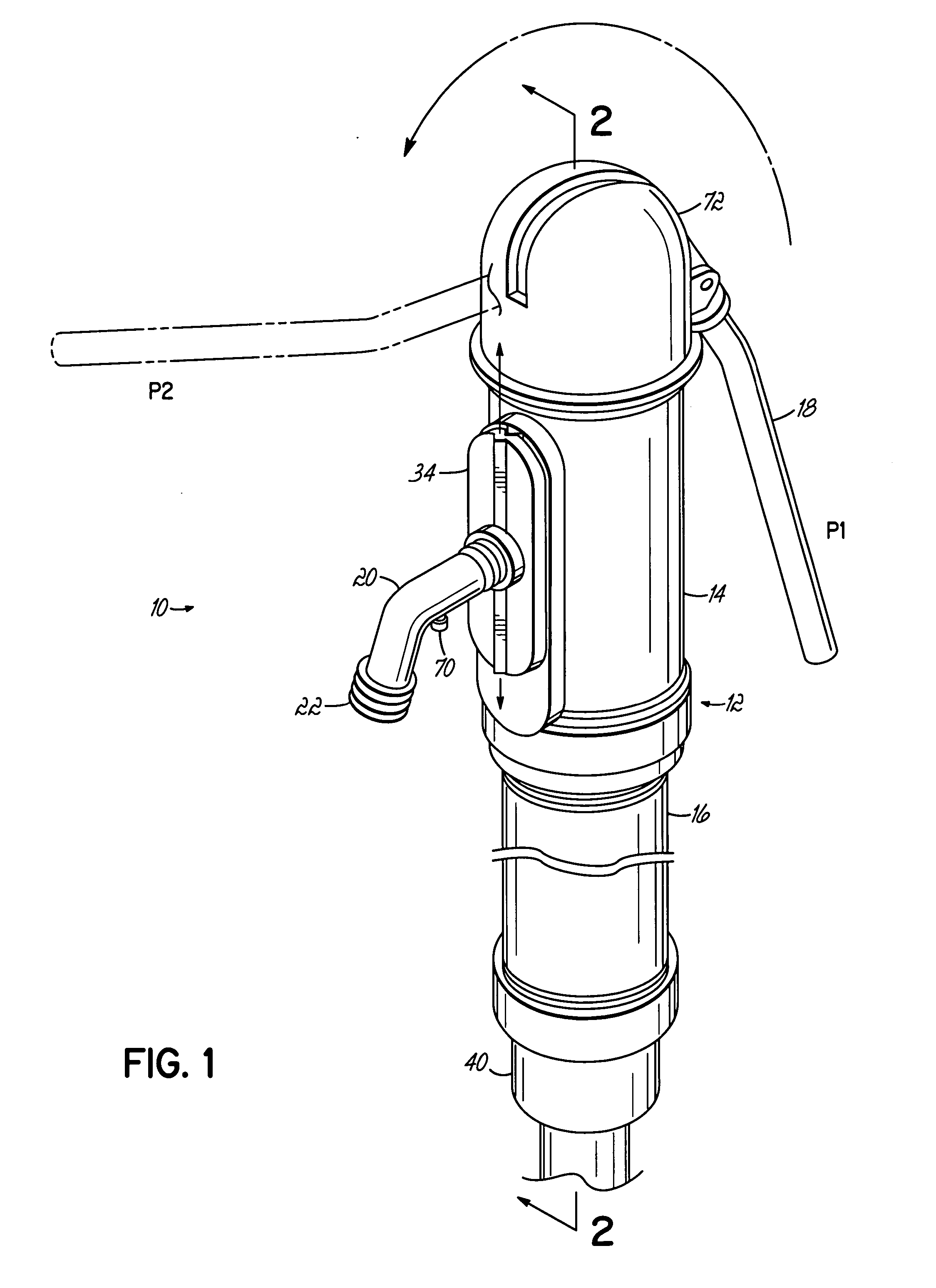
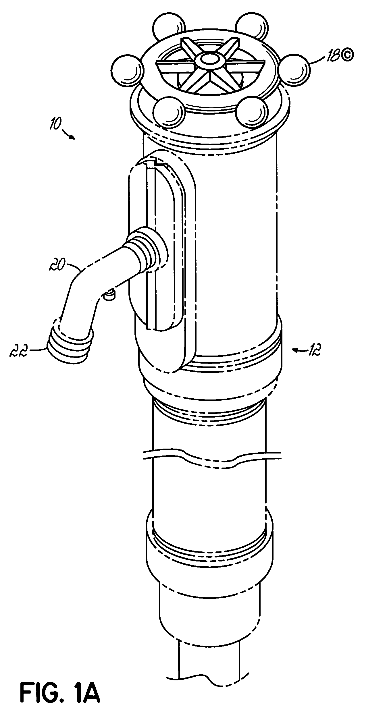
[0018] Referring to FIG. 1, there is shown an exemplary water hydrant 10 of the present invention. The hydrant 10 includes a housing 12 which has an upper casing 14 that is generally exposed above the ground, and an elongate pipe 16 which extends from the upper casing 12 beneath the ground. The hydrant 10 further includes a handle 18 for operating the hydrant 10 and a spigot 20, having an outlet 22, for dispensing water from a water supply. In an exemplary embodiment, the handle 18 of the hydrant 10 is a lever type handle, but may be of other types such as a rotary knob 18′, as depicted in FIG. 1A, or any other suitable device for manipulating the hydrant elements described herein.

[0019] Referring further to FIG. 2, the handle 18 is pivotally mounted to a shaft 19 and is coupled to a riser 24 contained within the housing 12. The riser 24 extends from the upper casing 14 through the pipe 16 and is movable to engage a valve assembly 30 located beneath the surface and coupled to the w...


PUM


Abstract

A water hydrant for suppling potable water from a water source has an internal movable riser contained within a housing that extends beneath the ground to a depth below which freezing temperatures cannot reach. A chamber housing located at a distal end of the hydrant, beneath the frost line, contains a valve which may be actuated by the moving riser to provide a flow of water from the water source and through the riser. The chamber housing is configured to receive residual water from the riser when the flow of water has been shut off by the valve and to store the water beneath the frost line under sanitary conditions. A piston is disposed on a distal end of the riser, is slidably disposed within the chamber housing, and moves with the riser to expel water from the chamber housing when a handle of the hydrant is subsequently moved to reopen the valve.

Description

CROSS-REFERENCE TO RELATED APPLICATION [0001] This application claims priority to U.S. Provisional Application Ser. No. 60 / 542,766 filed on Feb. 6, 2004, incorporated herein by reference in its entirety.FIELD OF THE INVENTION [0002] This present invention relates to water hydrants and, more particularly, to a sanitary water hydrant for supplying potable water from a water supply. BACKGROUND OF THE INVENTION [0003] Outdoor water hydrants are useful for supplying potable water in various locations, such as parks, farms, railroad yards and various other outdoor settings. Because the water dispensed from such hydrants may be consumed by humans or animals, the water must be provided from the water source under sanitary conditions. Thus, care must be taken that the hydrant is sealed from the surrounding environment against leaks into the hydrant or water supply. If these outdoor hydrants are used with hoses, they are often fitted with vacuum breakers to prevent back flow of water from the...

Claims


Application Information

Patent Timeline
IPC IPC(8): E03B9/04F16K27/00
CPCF16K27/006E03B9/04Y10T137/5497Y10T137/0318Y10T137/538Y10T137/5415
Inventor MURDOCK, ROBERT A.
Owner MURDOCK INC
Why Eureka
Try Eureka