
Earth penetrating apparatus and method employing radar imaging and rate sensing

a technology of radar imaging and rate sensing, applied in the field of earth-penetration equipment, can solve the problems of damage to previously buried utilities, structures or roadways disturbed by digging trenches, and rarely restored to their original condition

Inactive Publication Date: 2005-08-11
VERMEER MFG CO
View PDF87 Cites 52 Cited by
  • Summary
  • Abstract
  • Description
  • Claims
  • Application Information

AI Technical Summary

Problems solved by technology

In areas supporting existing construction, a trench can cause serious disturbance to structures or roadways.
Further, there is a high probability that digging a trench may damage previously buried utilities, and that structures or roadways disturbed by digging the trench are rarely restored to their original condition.
Also, an open trench poses a danger of injury to workers and passersby.
It can be appreciated that present methods of detecting and controlling boring tool movement along a desired underground path is cumbersome, fraught with inaccuracies, and require repeated halting of boring operations.
Moreover, the inherent delay resulting from verbal communication of course change instructions between the operator of the locator and the boring machine operator may compromise tunneling accuracies and safety of the tunneling effort.
By way of example, it is often difficult to detect the presence of buried objects and utilities before and during tunneling operations.
In general, conventional boring systems are unable to quickly respond to needed boring tool direction changes and productivity adjustments, which are often needed when a buried obstruction is detected or changing soil conditions are encountered.
It can be further appreciated that the human factor associated with such approaches results in a relatively slow response time to changing well conditions and reduced surveying accuracies.
Such dependency on human intervention within the control loop of a drilling system generally decreases overall excavation productivity, increases the delay time to effect necessary changes in drilling system activity in response to acquired drilling machine and drill head sensor information, and increases the risk of injury to operators and the likelihood of operator error.

Method used


Image

  • Earth penetrating apparatus and method employing radar imaging and rate sensing
  • Earth penetrating apparatus and method employing radar imaging and rate sensing
  • Earth penetrating apparatus and method employing radar imaging and rate sensing

Examples


first embodiment

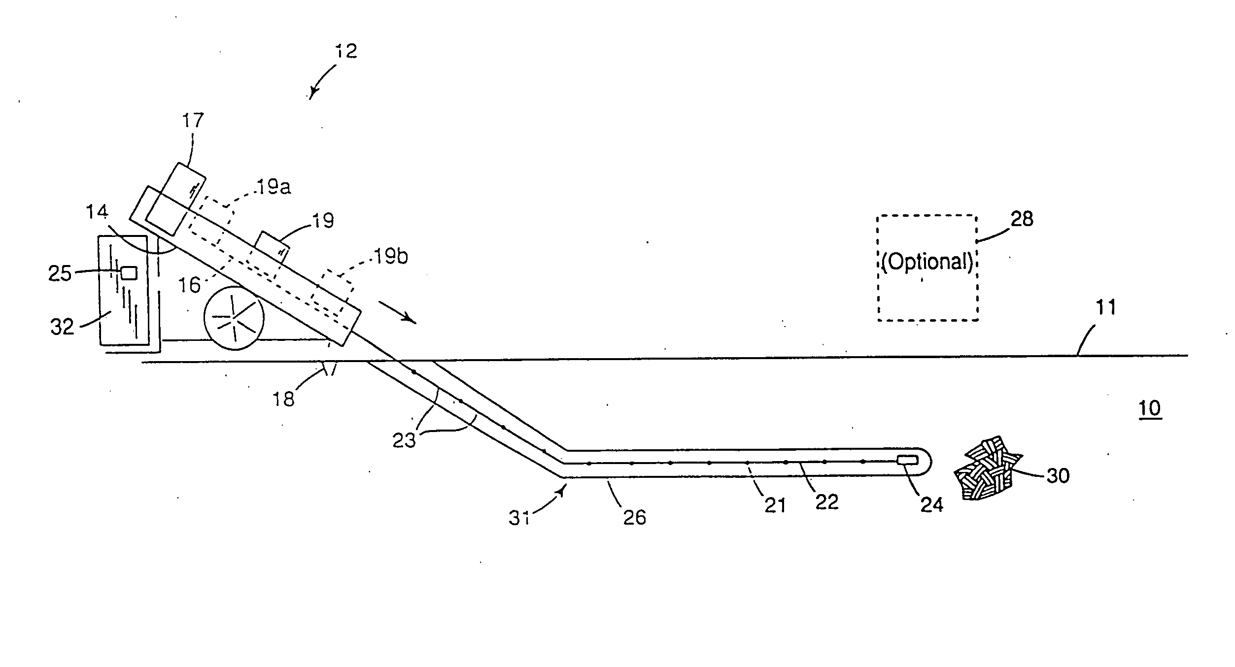
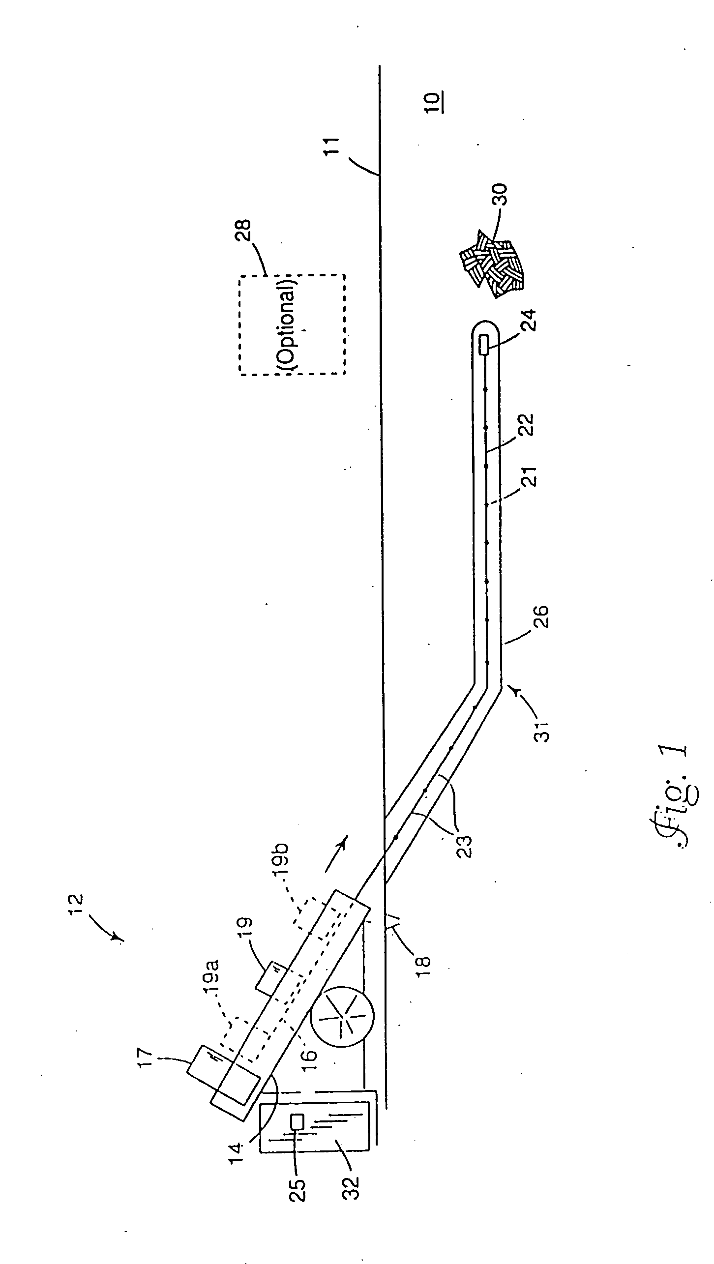
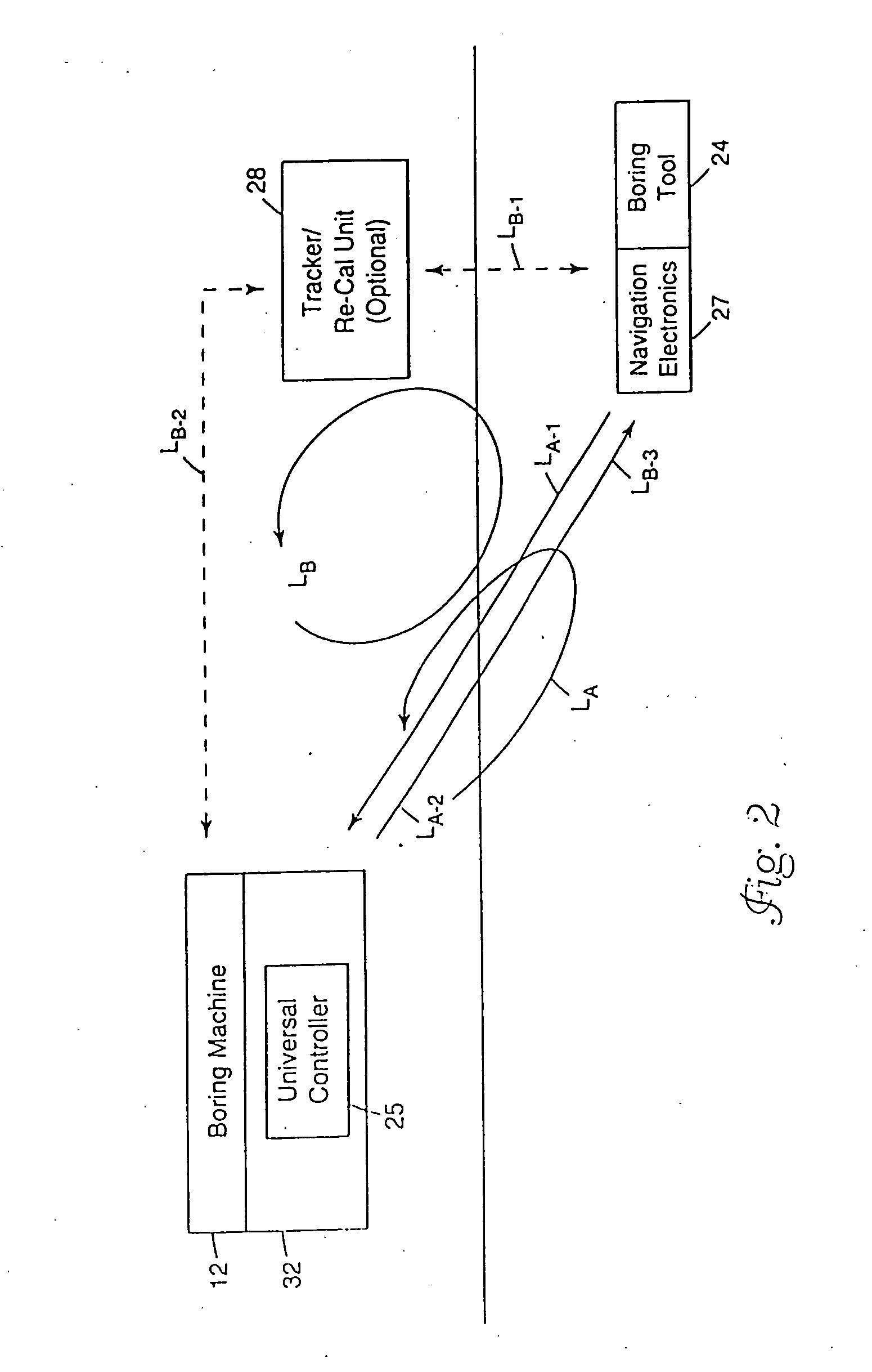
[0089]FIG. 2 illustrates an important aspect of the present invention. In particular, FIG. 2 depicts various embodiments of a closed-loop control system as defined between the boring machine 12 and the boring tool 24. According to one embodiment, communication of information between the boring machine 12 and the boring tool 24 is facilitated via the drill string. A control loop, LA, illustrates the general flow of information through a closed-loop boring control system according to the present invention. The navigation sensor package 27 provided in the boring tool 24 acquires location and orientation data. The acquired data may be processed locally within the navigation sensor package 27. The data acquired at the boring tool 24 is transmitted as an information signal along a first loop segment, LA-1, and is received by the boring machine 12. The received information signal is processed by the universal controller 25 typically provided in a control unit 32 of the boring machine 12. C...

second embodiment

[0091] In accordance with a second embodiment, a closed-loop control system is defined between the boring machine 12, boring tool 24, and tracker unit 28. A control loop, LB, illustrates the general flow of information through this embodiment of a closed-loop control system of the present invention. The boring tool 24 transmits an information signal along a first loop segment, LB-1, which is received by the tracker unit 28. In response to the received information signal, the tracker unit 28 transmits an information signal along a second loop segment, LB-2, which is received by the universal controller 25. The received information signal is processed by the universal controller 25 of the boring machine 12. In response to the processed information signal, desired adjustments are made by the boring machine 12 to alter or maintain the activity of the boring tool 24, such adjustments being effected along a third loop segment, LB-3, of the control loop, LB. It is noted that the first and ...


PUM


Abstract

An earth penetrating apparatus includes a cutting tool and a sensor housing. A radar unit, rate sensor unit, processor, and transmitter are provided in the sensor housing. An antenna arrangement is coupled to the radar unit and configured for transmitting and receiving electromagnetic signals in a relatively forward and / or lateral looking direction relative to a distal end of the cutting tool. The rate sensor unit may include one or both of a gyroscope and an accelerometer. The processor receives radar data from the radar unit indicative of subsurface strata and obstacles respectively located generally forward and / or lateral of the cutting tool, and receives displacement data from the rate sensor unit indicative of one or both of longitudinal and rotational displacement of the cutting tool. The transmitter is configured for transmitting one or both of the radar data and the displacement data to an aboveground location.

Description

RELATED APPLICATIONS [0001] This is a continuation of patent application Ser. No. 10 / 817,202 filed on Apr. 2, 2004, which is a divisional of patent application Ser. No. 10 / 304,185 filed on Nov. 25, 2002, now U.S. Pat. No. 6,719,069, which is a divisional of patent application Ser. No. 09 / 867,952 filed on May 30, 2001, now U.S. Pat. No. 6,484,818, which is a divisional of patent application Ser. No. 09 / 405,890 filed on Sep. 24, 1999, now U.S. Pat. No. 6,315,062, which are respectively hereby incorporated by reference herein.FIELD OF THE INVENTION [0002] The present invention relates generally to the field of underground boring and, more particularly, to an earth penetrating apparatus that includes a cutting tool and a sensor unit for facilitating subsurface imaging and for determining cutting tool location. BACKGROUND OF THE INVENTION [0003] Utility lines for water, electricity, gas, telephone and cable television are often run underground for reasons of safety and aesthetics. In man...

Claims


Application Information

Patent Timeline
IPC IPC(8): E21B7/04E21B7/08E21B44/00E21B47/022
CPCE21B7/046E21B17/028E21B47/022E21B44/005E21B44/00E21B7/28
Inventor ALFT, KEVIN L.DRAPER, GREGORY W.KELPE, HANS
Owner VERMEER MFG CO
Learn More