Positive drive handrail assembly

a technology of positive drive and handrail, which is applied in the direction of conveying, escalators, transportation and packaging, etc., can solve the problems of handrail slipping or disintegration, the bond between the plies and tensile elements cannot withstand the drive force of a drive mechanism, and the type of laminated structure can be costly to manufacture, so as to improve the durability of handrail and drive, and reduce the amount of stress on the handrail structure.

Inactive Publication Date: 2005-08-11
BALL RONALD H
View PDF15 Cites 50 Cited by
  • Summary
  • Abstract
  • Description
  • Claims
  • Application Information

AI Technical Summary

Benefits of technology

[0009] This invention provides an improved handrail construction for escalators and moving walkways that enables the handrail to be advanced b

Problems solved by technology

Unfortunately, this type of laminated structure can be costly to manufacture since the extra plies of fabric must be coated with adhesive and adhered to the adjacent plies and hard rubber layers.
In many instances, the bond between the plies and tensile elements cannot withstand the drive forces imposed by a drive mechanism.
As a result, the plies of the handrail may delaminate causing the handrail to slip or disintegrate.
This improvement removes the possibility of delamination but the problem of wear due to friction and slippage between it and the drive remain.
As the escalator drive depends on the grip between its surface and the low friction fabric, this further makes the task of driving the handrail more difficult.
While this design provides adequate transmission of drive forces, passing the

Method used


Image

  • Positive drive handrail assembly
  • Positive drive handrail assembly
  • Positive drive handrail assembly

Examples


first embodiment

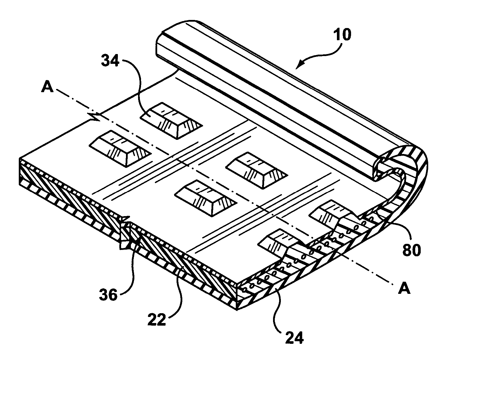
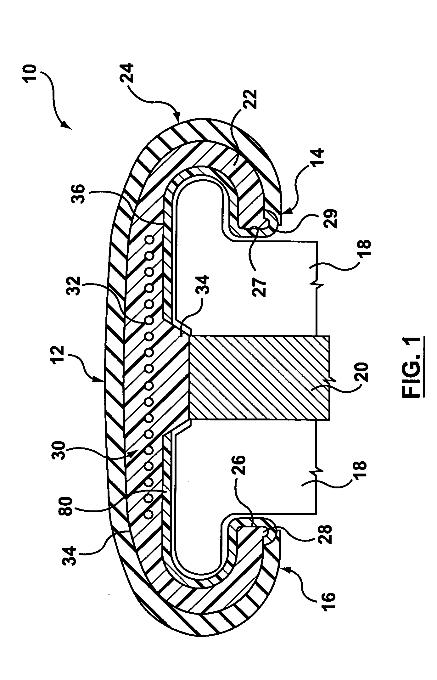
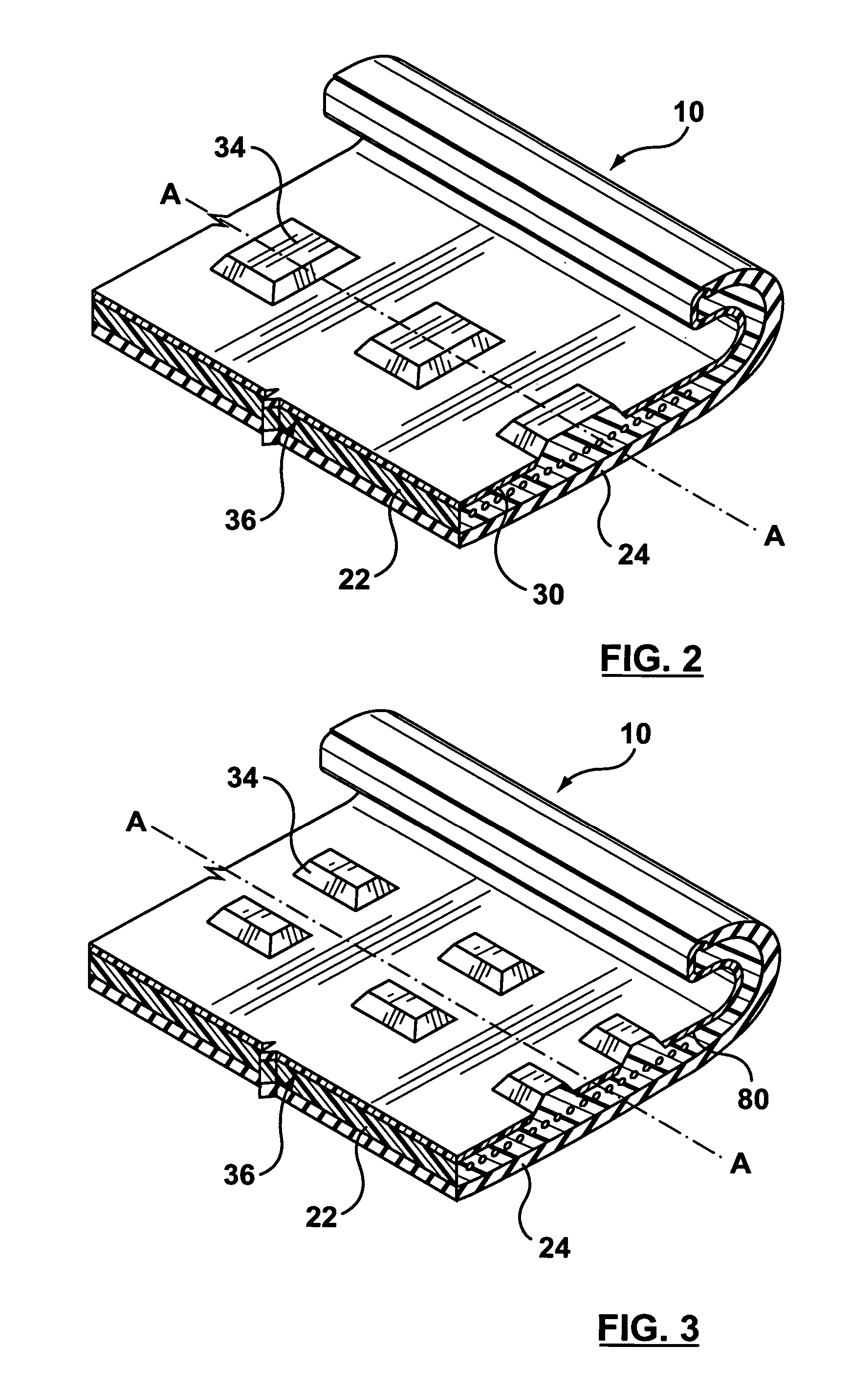
[0032] Now, in accordance with a first embodiment, of the present invention, the handrail 10 is provided with a plurality of teeth 34 which engage with the drive means 20 to drive the handrail 10. The plurality of teeth 34 extend generally perpendicularly from an inner surface 36 of the inner layer 22. In use in the orientation of FIG. 1, the inner surface forms a bottom surface of the handrail and partially defines a T-shaped slot that forms part of a conventional handrail design. While the teeth 34 shown are trapezoidal in transverse and longitudinal cross-section, it is understood that any tooth cross-section that provides an engaging surface may be used, such as, for example, rectangular, pyramidal, sinusoidal cross-sections or any other geometric solid. Any conventional tooth profile, such as an involute profile, can be used. Referring to FIG. 2, the teeth 34 may be aligned in a row along the longitudinal axis A-A of the handrail 10. Alternatively, the handrail 10 may be provid...

second embodiment

[0037] In this second embodiment, the slider fabric is shown as not extending into the groove 38, i.e. as two strips on either side. However, the slider fabric 80 could extend into the groove 38 at least up to the edge of the teeth 34. It could even cover the teeth 34, to at least some extent.

[0038] The handrail 10 made in accordance with the second embodiment of the present invention may be used to retrofit a conventional escalator. Typically, the guide on a conventional escalator has a generally planar surface that contacts the flat inner surface of the handrail. The teeth 34 are recessed into the inner layer 22 and below the level of the fabric slider surface 80 and are therefore able to slide smoothly along the planar surface of the conventional guide 18. Since the replacement of the original guide is not necessary, the costs associated with the conversion of a conventional escalator to a positive drive system would be limited.

[0039] Alternatively, a conventional handrail may b...


PUM


Abstract

This invention provides an improved handrail construction for escalators and moving walkways that enables the handrail to be advance by positive drive forces so as to reduce the amount of stress on the handrail structure and to improve the durability of escalator handrail systems. The handrail includes teeth for engaging a drive mechanism, the teeth preferably being formed in the body of the handrail.

Description

FIELD OF THE INVENTION [0001] This invention relates to moving handrails for escalators, moving walkways and similar transportation apparatus. More particularly, the invention relates to a positive drive assembly for moving handrails for such transportation apparatus. BACKGROUND OF THE INVENTION [0002] Handrails for escalators, moving walkways and other similar transportation enable passengers to travel safely between the floors or along the corridors of a building. To operate safely, the handrail must move uniformly with the escalator stairs or walkway and provide a firm grip for the passengers. Structurally, the handrail must be strong enough to withstand high tensile and compressive forces imposed by the drive mechanism of the escalator system. In use, an escalator handrail drive mechanism must operate without slippage between the handrail and drive mechanism so that the handrail is not damaged by friction and wear from the drive. [0003] A common conventional handrail has a C-sha...

Claims


Application Information

Patent Timeline
IPC IPC(8): B66B23/04B66B23/20B66B23/22B66B23/24B66B31/02
CPCB66B23/04B66B23/24B66B23/225
Inventor CAUNCE, A. STUART
Owner BALL RONALD H
Why Eureka
Try Eureka