Eureka AIR delivers breakthrough ideas for toughest innovation challenges, trusted by R&D personnel around the world.

Rotating toilet tool holder

a technology for toilet tools and holder covers, which is applied in the direction of rigid containers, packaging, transportation and packaging, etc., can solve the problems of irritating the toilet and creating both sanitary and aesthetic problems, unable to sanitize the plunger after each use, and moisture or residue remaining on the plunger after recent use often drips or runs to the floor, so as to reduce rotational friction

Active Publication Date: 2005-08-11
HOMEWERKS WORLDWIDE LLC
View PDF7 Cites 27 Cited by
  • Summary
  • Abstract
  • Description
  • Claims
  • Application Information

AI Technical Summary

Benefits of technology

[0014] The main body may include means for reducing rotational friction between the base and the rotating member. The rotating member may be rotatably mounted within the main body.

Problems solved by technology

These known uses inherently create both sanitary and aesthetic issues for any party responsible for bathroom maintenance.
In most application settings, it is unrealistic to sanitize the plunger after each use.
As a result, moisture or residue remaining on the plunger after recent use often drips or runs to the floor.
Further, the plunger itself is unsightly and may contrast with the decorum of certain bathrooms.
Some involve relatively expensive and rather complicated sanitizing systems.
These devices either do not entirely hide the plunger, or are difficult for some users to open and close during plunger transfer.
It should be appreciated that a device becomes unsanitary after contact with a used plunger and any design that requires a user to touch the holder is not desired.
Also, certain prior art designs are not easily transportable from one location to another when the toilet tool is in storage within the device.
In regard to other types of toilet related tools, similar inherent problems exist with storage devices known in the art that are designed for brushes and other tools.

Method used


Image

  • Rotating toilet tool holder
  • Rotating toilet tool holder
  • Rotating toilet tool holder

Examples


Embodiment Construction

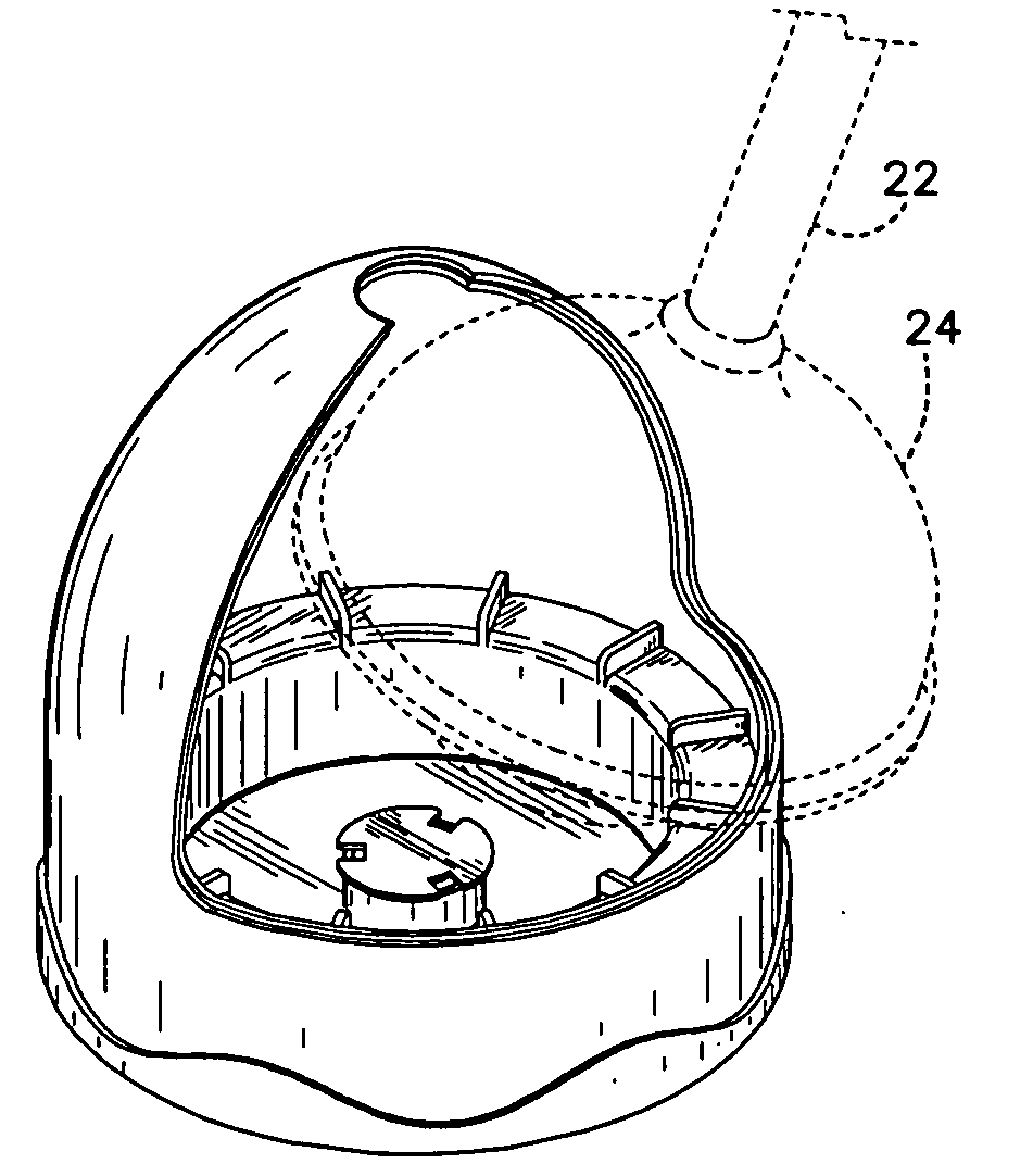
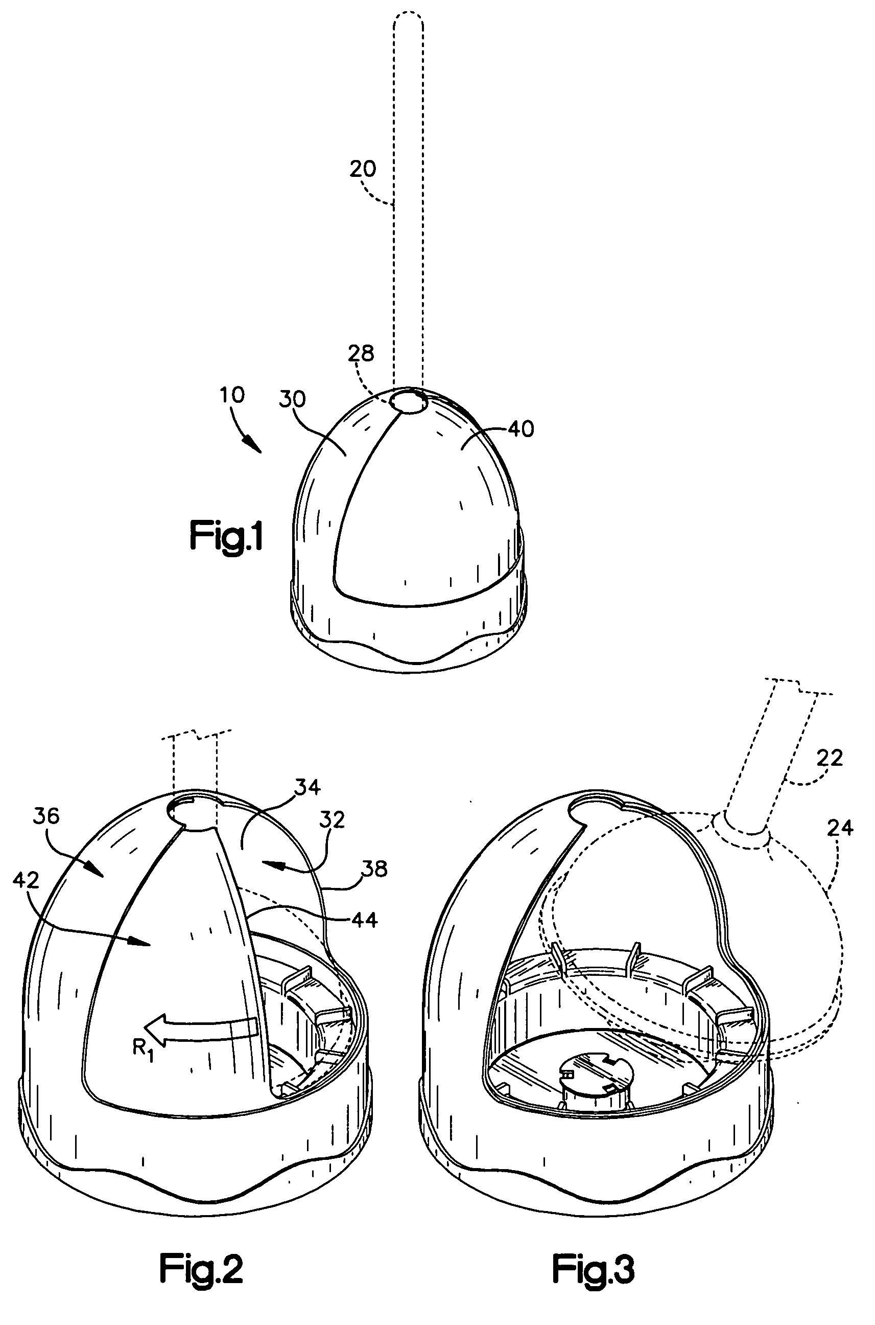
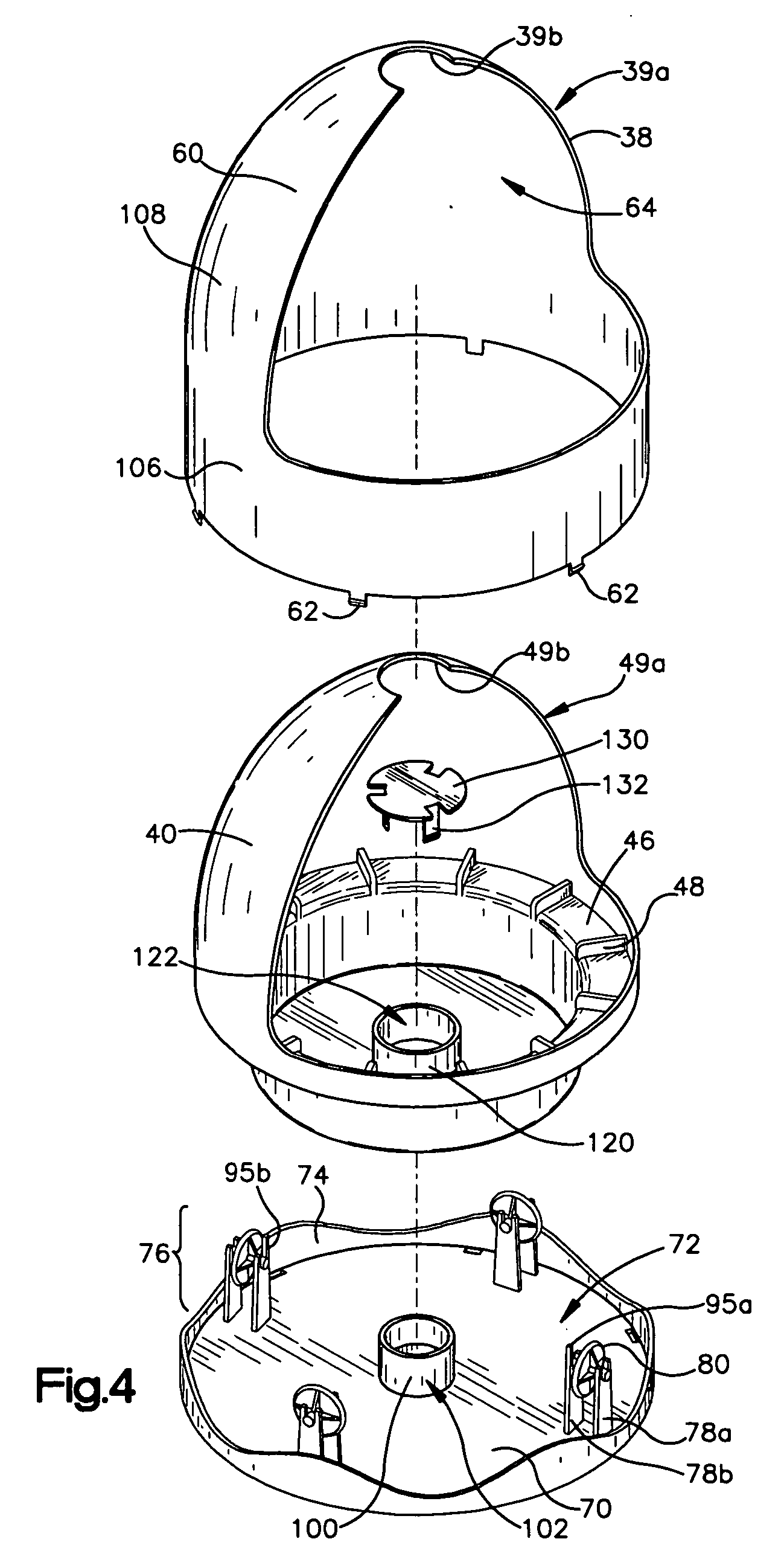
[0025] Referring now to the drawings, a plunger holder 10 constructed in accordance with one embodiment of the present invention is illustrated. The holder 10 proves accessible storage for a plunger 20. It should be understood that the illustration of a plunger is for exemplary purposes only, and that the present invention may be practiced with the use of a toilet brush or any type of toilet tool having a handle and an implement.

[0026] The holder 10 provides an innocuous looking, closeable assembly that can be positioned on the floor adjacent to a toilet. The holder 10 can be advantageously opened and closed by an operator by rotation of the plunger handle 22. Rotation of the plunger handle causes rotation of one moveable part of the device with respect to another part of the device which may be fixed.

[0027] Referring to FIG. 1, a perspective view of a rotating plunger holder 10 constructed in accordance with one embodiment of the present invention is shown. A plunger 20 in dashed...


PUM


Abstract

A toilet tool storage device for providing accessible and transportable storage for a tool having an implement and a handle is disclosed. The device includes a first shell and a second shell. The first shell has an inner surface defining a receptacle sized to house the implement and an outer surface defining a first opening. The second shell is rotatably engaged to the first shell and has an outer surface defining a second opening. The second shell is rotatable between a first position and a second position. In the first position, the first opening and the second opening are cooperatively aligned to provide access to the receptacle so that the tool may be moved in or out of the receptacle. In the second position, the outer surface of the second shell and the first opening are cooperatively aligned prohibit access to the receptacle, thereby enclosing the implement.

Description

FIELD OF THE INVENTION [0001] The present invention relates to a storage device and more particularly to a toilet tool storage device having rotational features for providing access to a tool stored within the device. BACKGROUND OF THE INVENTION [0002] Tools designed for use with toilets, such as plungers and scrub brushes, are well-known and widely-used in bathrooms of residences, office buildings, retail establishments and restaurants. Of course, toilet brushes are used to clean the interior of a toilet bowl. It is further known and appreciated that the conventional use of a plunger is to unclog the exit piping leading from a toilet to a sewer system or other types of collection system. These known uses inherently create both sanitary and aesthetic issues for any party responsible for bathroom maintenance. [0003] In regard to plungers, it is common to store a plunger on the floor adjacent to a toilet in a conveniently locatable site. In most application settings, it is unrealistic...

Claims


Application Information

Patent Timeline
Patent Type & Authority Applications(United States)
IPC IPC(8): A45C11/26A47K17/00E03C1/308E03D9/00
CPCA47K17/00
Inventor RICH, RONALD
Owner HOMEWERKS WORLDWIDE LLC
Why Eureka
Eureka Blog
Learn More