Cooking appliance
- Summary
- Abstract
- Description
- Claims
- Application Information
AI Technical Summary
Benefits of technology
Problems solved by technology
Method used
Image

Examples
first embodiment
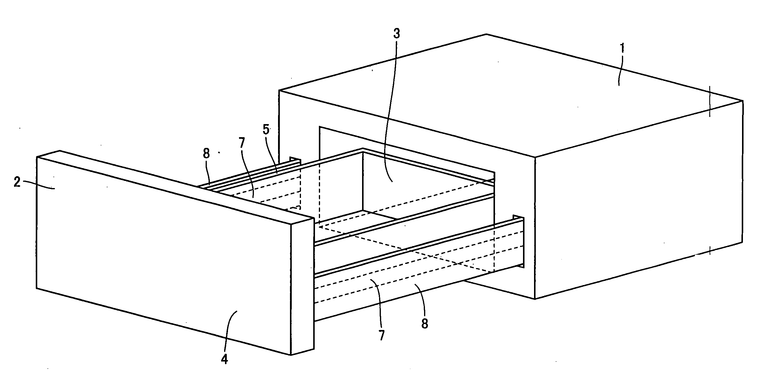
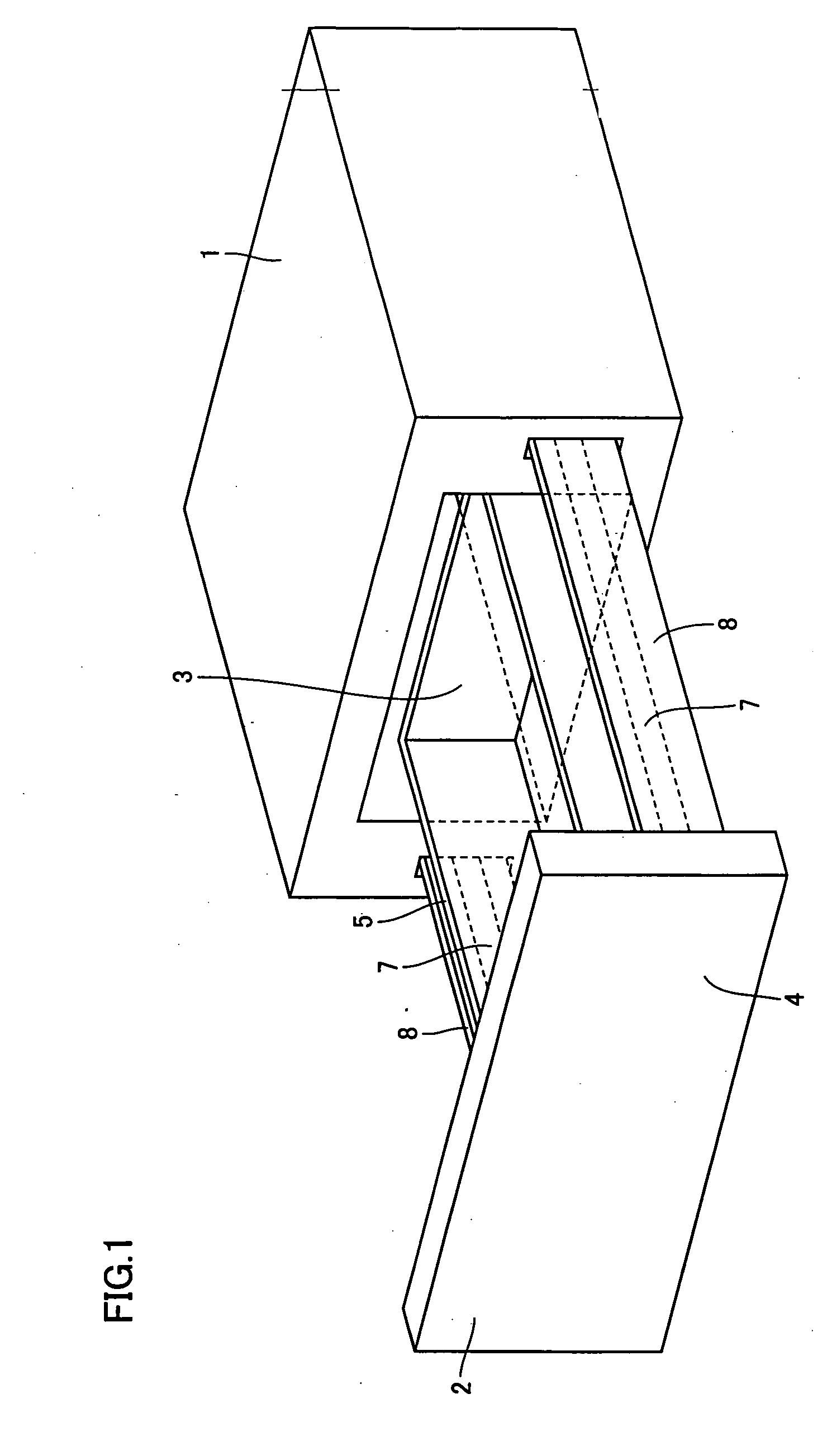
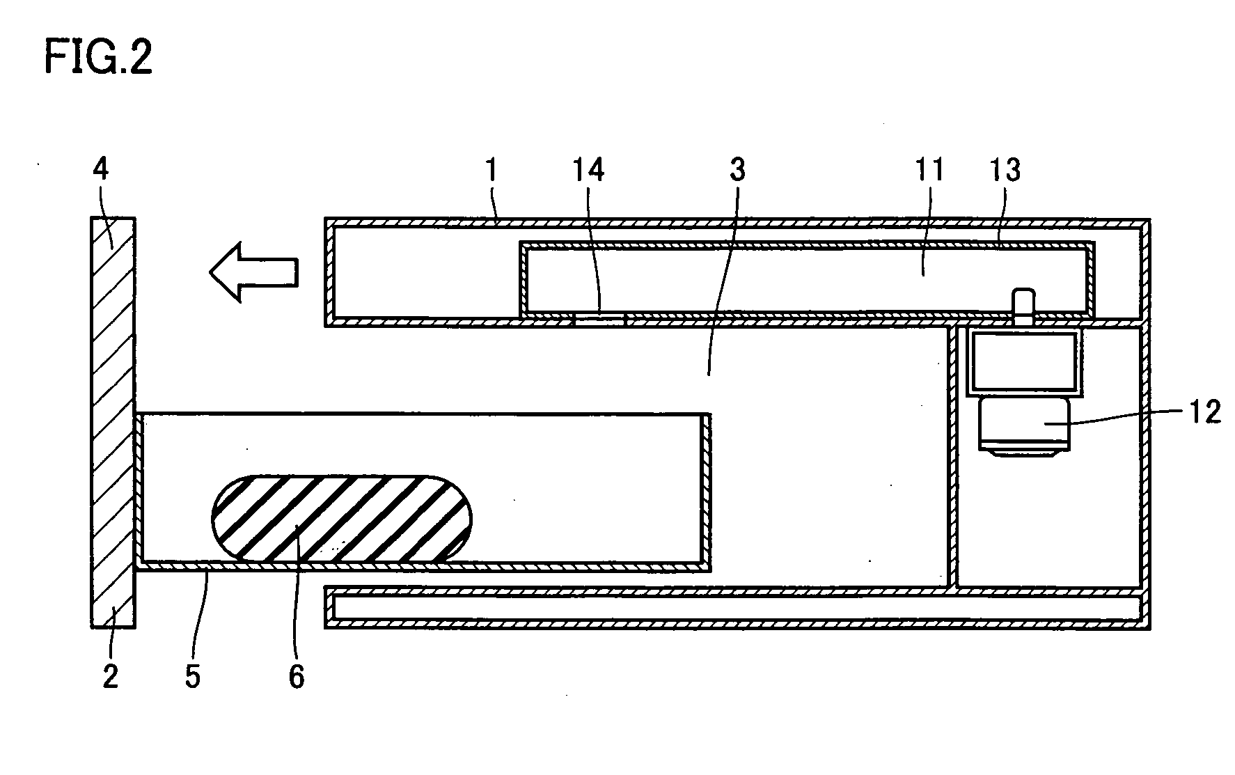
[0034] Referring to FIGS. 1, 2 and 3, a main unit 1 of a cooking appliance according to the present invention includes a heating chamber 3 to cook an item to be heated 6. A drawer unit 2 is arranged in a movable manner, i.e. slidable manner, in main unit 1 so as to be withdrawn from heating chamber 3 of main unit 1 in the direction indicated by the arrow. The cooking appliance includes a slide rail 7 identified as the transfer mechanism to slide drawer unit 2 in main unit 1. Drawer unit 2 includes a door 4 to open / close heating chamber 3, and a heating receptacle 5 in which item 6 is placed and held. Heating receptacle 5 includes sidewalls at the left and right sides, a rear wall at the back in heating chamber 3 of main unit 1, and an opening at the top. Door 4 is attached at the front of heating receptacle 5. By closing heating chamber 3 through door 4, the interior cavity of heating chamber 3 corresponds to a sealed cavity by the inner walls of main unit 1 and drawer unit 2.
[0035]...
second embodiment
[0041]FIG. 4 is a plan sectional view of a cooking appliance according to the present invention in a direction parallel to the pulling out direction of the drawer unit.
[0042] In comparison with the first embodiment in which fixed rail 9 is attached to the inner wall surface of main unit 1 outside and closer to heating chamber 3, fixed rail 9 can be attached to an inner wall surface constituting the contour wall of main unit 1 outside and distant from heating chamber 3 as in the second embodiment shown in FIG. 4. The advantages similar to those of the first embodiment can be attained for the second embodiment.
third embodiment
[0043] A cooking appliance according to the present invention is shown in FIG. 5.
[0044] In addition to slide rail 7 provided at the left and right sidewalls surfaces outside heating chamber 3 as a transfer mechanism, door 4 of drawer unit 2 is supported on main unit 1 by the bottom wall surfaces outside heating chamber 3 via a slide rail 15. Slide rail 15 includes a fixed rail 15a and a movable rail 15b sliding along fixed rail 15a. Fixed rail 15a is attached to the bottom wall surfaces outside heating chamber 3 of main unit 1. Movable rail 15b is attached to door 4 via an L-shaped angle member 8a attached to the inner sidewall surface of door 4 so as to extend from the inner sidewall surface of door 4 of drawer unit 2 towards heating chamber 3 of main unit 1.
[0045] The third embodiment is characterized in that, as the transfer mechanism, slide rail 15 formed of fixed rail 15a and movable rail 15b is attached to the bottom wall surface outside heating chamber 3, in addition to slid...
PUM
 Abstract
Description
Claims
Application Information
 - Generate Ideas
- Intellectual Property
- Life Sciences
- Materials
- Tech Scout
- Unparalleled Data Quality
- Higher Quality Content
- 60% Fewer Hallucinations
Browse by: Latest US Patents, China's latest patents, Technical Efficacy Thesaurus, Application Domain, Technology Topic, Popular Technical Reports.
© 2025 PatSnap. All rights reserved.Legal|Privacy policy|Modern Slavery Act Transparency Statement|Sitemap|About US| Contact US: help@patsnap.com