Method and device for controlling or regulating the brake system of a motor vehicle according to the "brake by wire" principle

a technology of brake system and motor vehicle, applied in the field of vehicle brakes, can solve the problems of limited number of recognizable types of faults, safety of brake system by wire, and complex design, and achieve the effect of improving safety, reliability and availability

Inactive Publication Date: 2005-08-11
CONTINENTAL TEVES AG & CO OHG
View PDF9 Cites 29 Cited by
  • Summary
  • Abstract
  • Description
  • Claims
  • Application Information

AI Technical Summary

Benefits of technology

[0016] The braking requirement can be determined quickly by the measure according to the present invention, including a monitoring function that covers and quickly recognizes more types of faults than any known methods. Thus, safety, re

Problems solved by technology

A central issue with respect to these brake-by-wire systems is safety.
Even if certain faults can be detected with these known measures, which are based on diversity, the number of recognizable types of faults is still limited, as is the speed with which faults are detected.
Thus, the system disclosed calls for a s

Method used


Image

  • Method and device for controlling or regulating the brake system of a motor vehicle according to the "brake by wire" principle
  • Method and device for controlling or regulating the brake system of a motor vehicle according to the "brake by wire" principle
  • Method and device for controlling or regulating the brake system of a motor vehicle according to the "brake by wire" principle

Examples


Embodiment Construction

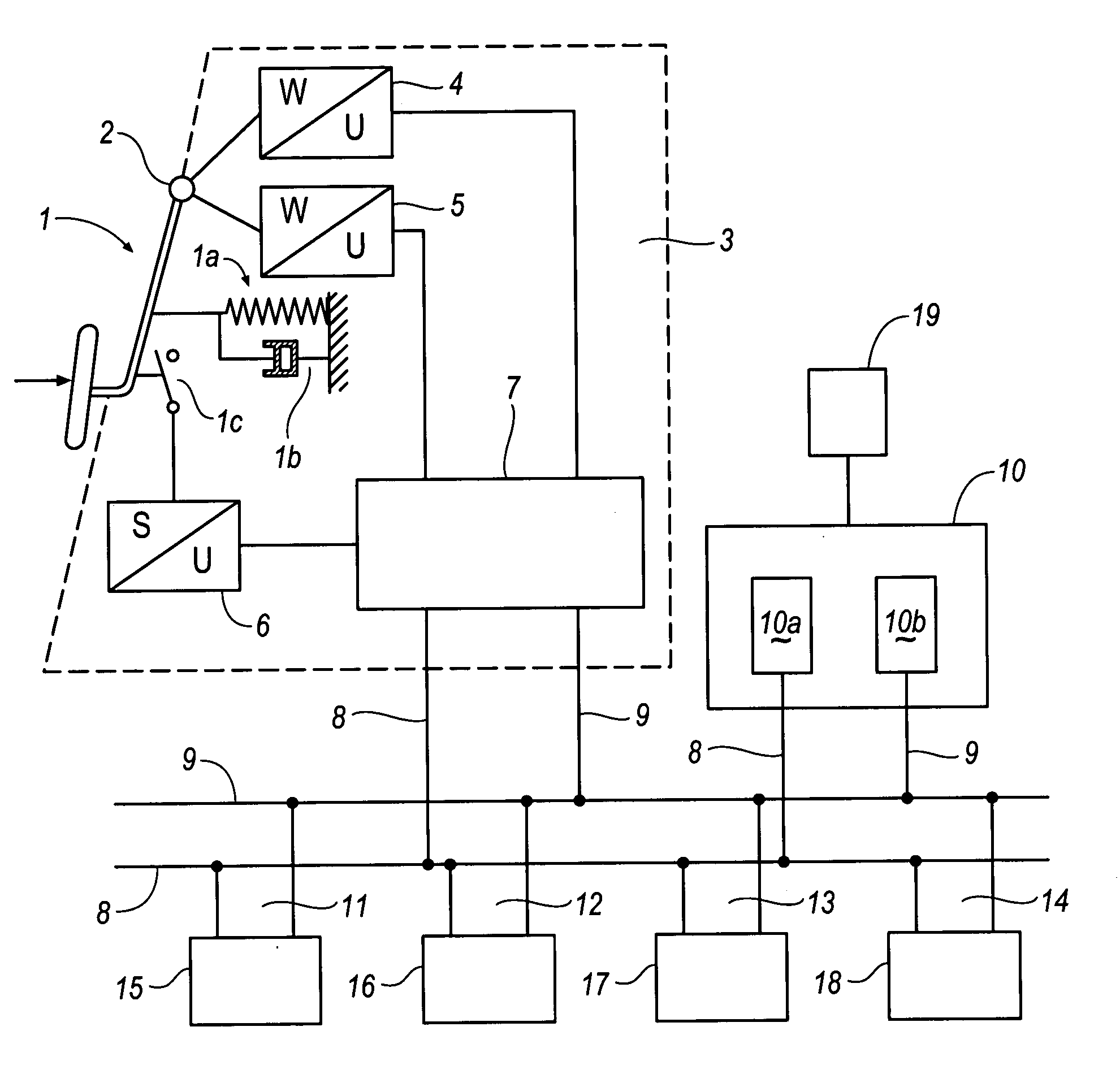
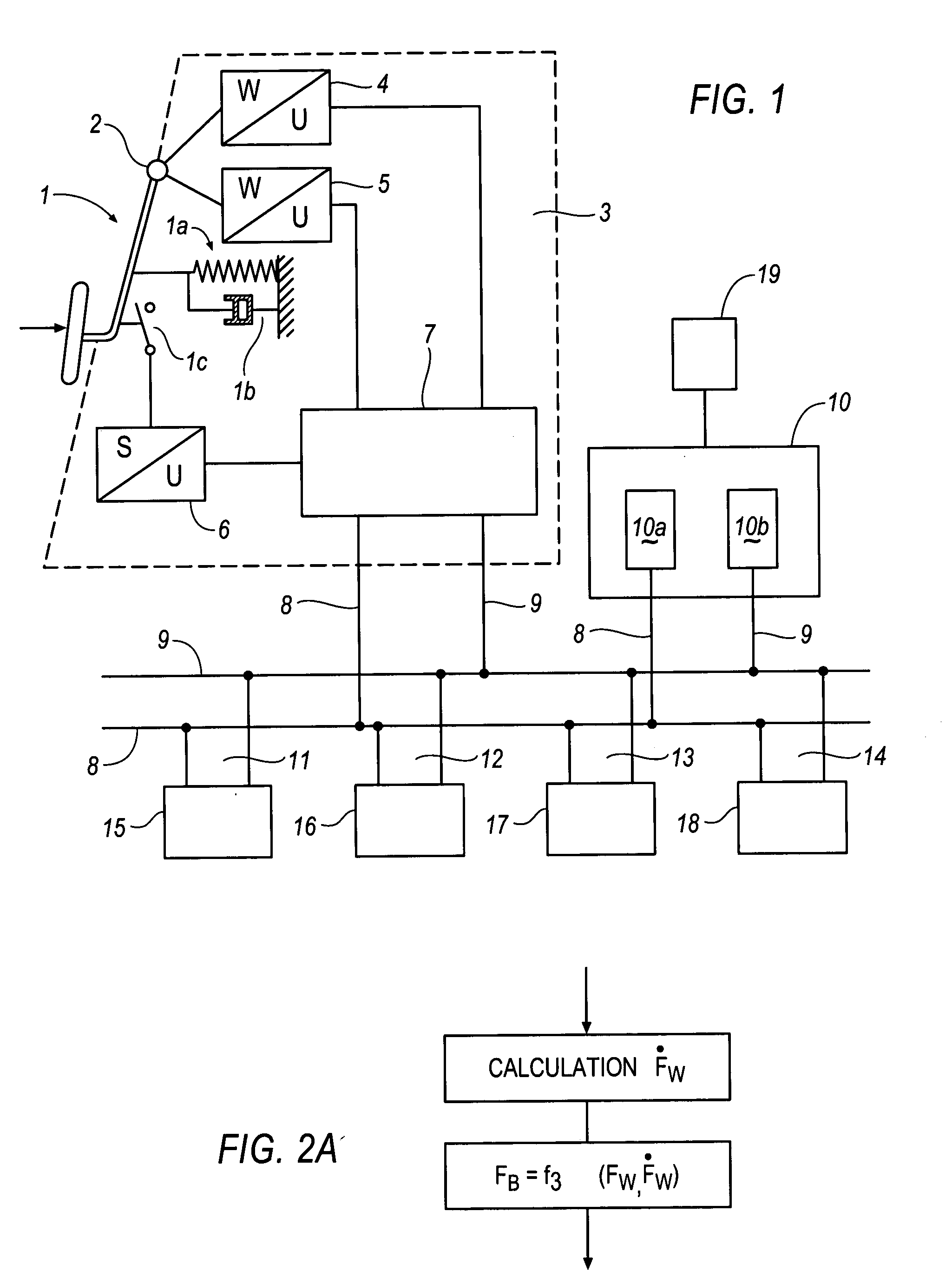
[0029]FIG. 1 shows a block diagram of the basic structure of a brake system according to the brake-by-wire principle of the present invention. The brake system exhibits a brake pedal 1 with a coupling having known mechanical pedal means, which reproduces the behavior of a conventional brake pedal that is connected mechanically to the brake system. These mechanical pedal means can be a mechanical element with a reset mechanism, e.g. a spring 1a. Reproduced hydraulic or pneumatic arrangements 1b are feasible, too. Characteristic of the pedal actuation is the foot force exerted by the driver, which is expressed in a corresponding pedal actuation force and / or the foot travel that is reflected in a corresponding brake pedal travel S or in a brake pedal angle W. These reproduced arrangements 1a, 1b can be single items or can be provided in duplicate form so as to increase the safety (redundancy). The characteristic values S or W for the pedal motion are sensed by a pedal module 3, which e...


PUM


Abstract

The most important aspect of brake systems in motor vehicles functioning according to the brake-by-wire principle is that the driver's braking requirements are detected quickly and reliably. Fulfilling this requirement primarily depends on the pedal sensor system associated with the brake pedal and its measuring devices for determining the characteristic values of the brake pedal actuation. The present invention provides for at least two measuring devices for determining the braking requirement, with such measuring devices sensing the same characteristic value of the brake pedal actuation, e.g. the brake-pedal actuation force, brake-pedal travel or brake-pedal angle. These braking requirement signals are compared to a signal from a third measuring device in order to monitor the braking requirement measuring devices.

Description

RELATED APPLICATIONS [0001] This application is a continuation-in-part of application Ser. No. 10 / 731,833 filed Dec. 9, 2003 which is a continuation-in-part of application Ser. No. 09 / 601,590 filed Feb. 3, 1999.TECHNICAL FIELD [0002] The present invention generally relates to vehicle brakes, and more particularly relates to a method for controlling or regulating the brake system of a motor vehicle according to the brake-by-wire principle. BACKGROUND OF THE INVENTION [0003] Normally brake systems for motor vehicles work according to the conventional principle of an hydraulic actuating device that is directly actuated by the brake pedal which is connected to the hydraulic wheel brakes. Similar to the principle of mechanically decoupling the control stick from the control rudders—known as the fly-by-wire principle—already applied in aircraft construction, designers of brake systems for motor vehicles also are trying to mechanically decouple the brake pedal from the brake system and int...

Claims


Application Information

Patent Timeline
IPC IPC(8): B60T7/04B60T8/32B60T8/60G06F7/00G06F17/00
CPCB60T8/3255B60T7/042
Inventor BOHM, JURGENSTOLZL, STEFANOEHLER, RAINER
Owner CONTINENTAL TEVES AG & CO OHG
Why Eureka
Try Eureka