Compact dynamoelectric machine

Active Publication Date: 2005-08-11
NIDEC SR DRIVES
View PDF13 Cites 24 Cited by
  • Summary
  • Abstract
  • Description
  • Claims
  • Application Information

AI Technical Summary

Benefits of technology

[0007] Among the several objects and features of the present invention may be noted the provision of a dynamoelectric machine which is compact in size; the provision of such a machine which operates efficiently; the

Problems solved by technology

Unfortunately, size constraints can reduce the generation of magnetic flux and torque.
These size constraints are superimposed on the need for highly efficient operation, and can produce conflicting design guidelines.
The latter degrades efficiency because additional electrical current brings an increase in iron and copper losses and related heat generation.
Further, the ferromagnetic materials cannot support infinite magnetic flux densities.
When the stator becomes magnetically saturated, an in

Method used


Image

  • Compact dynamoelectric machine
  • Compact dynamoelectric machine
  • Compact dynamoelectric machine

Examples


Example

[0020] Corresponding reference characters indicate corresponding parts throughout the views of the drawings.

DETAILED DESCRIPTION OF THE PREFERRED EMBODIMENT

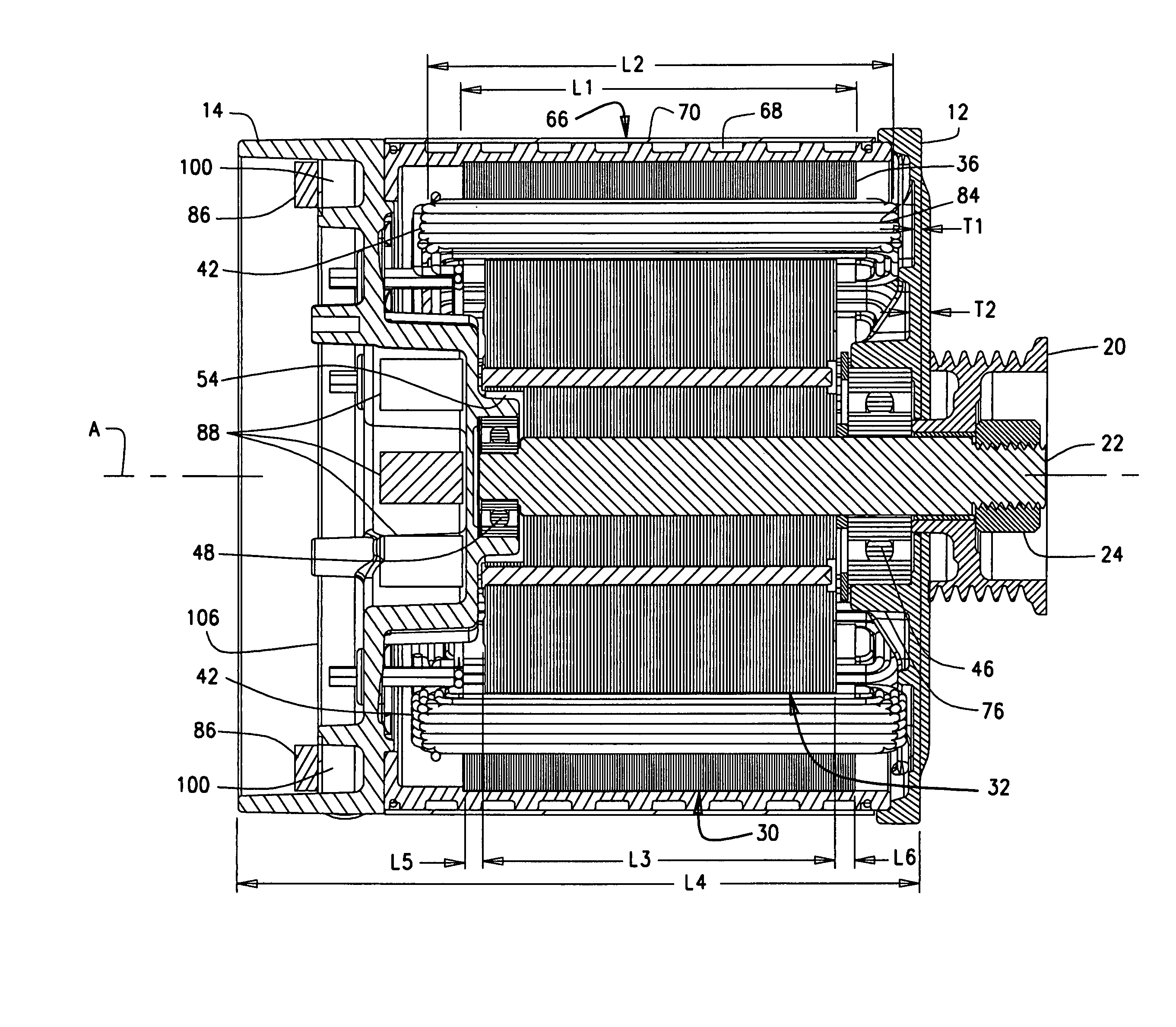
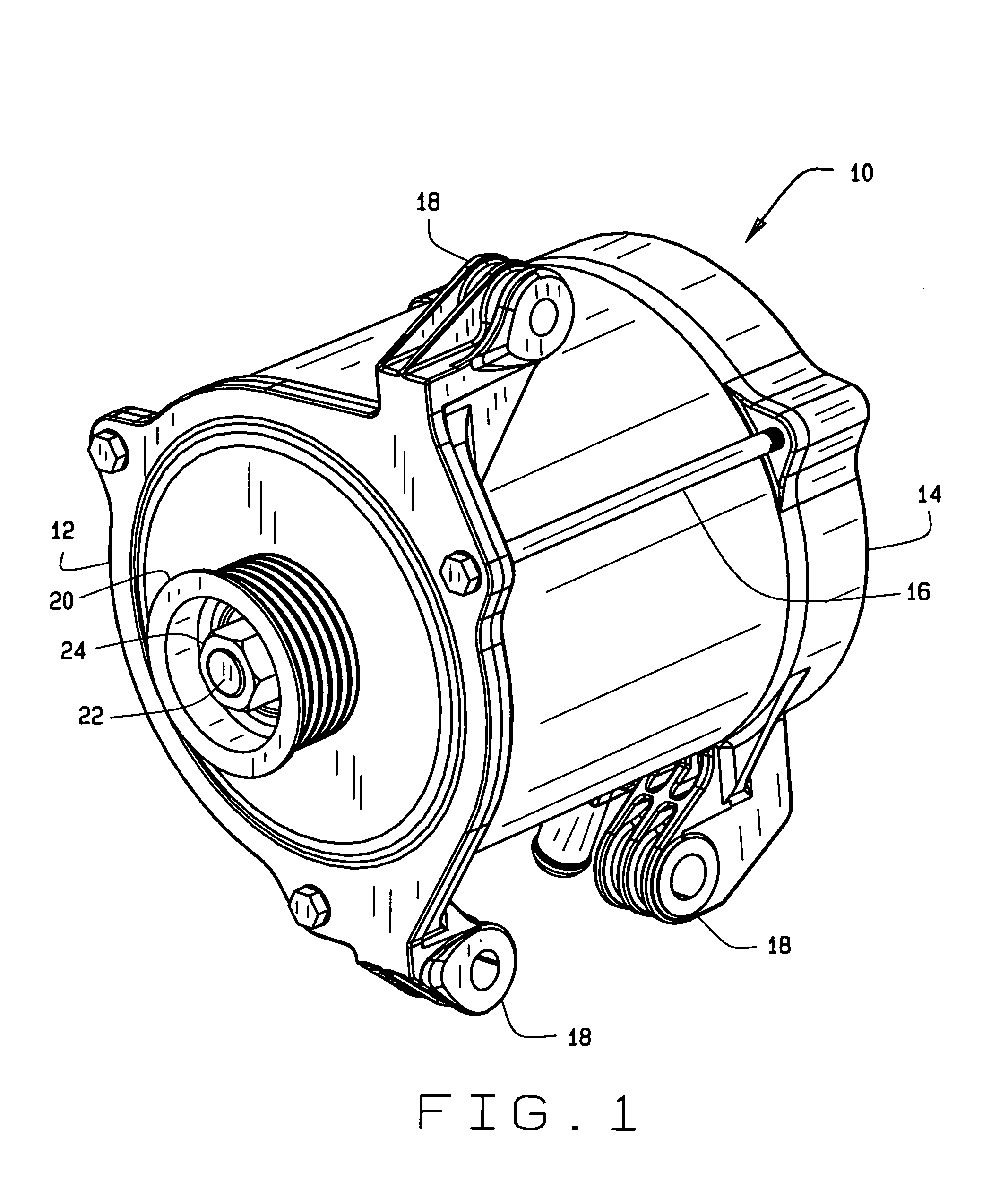
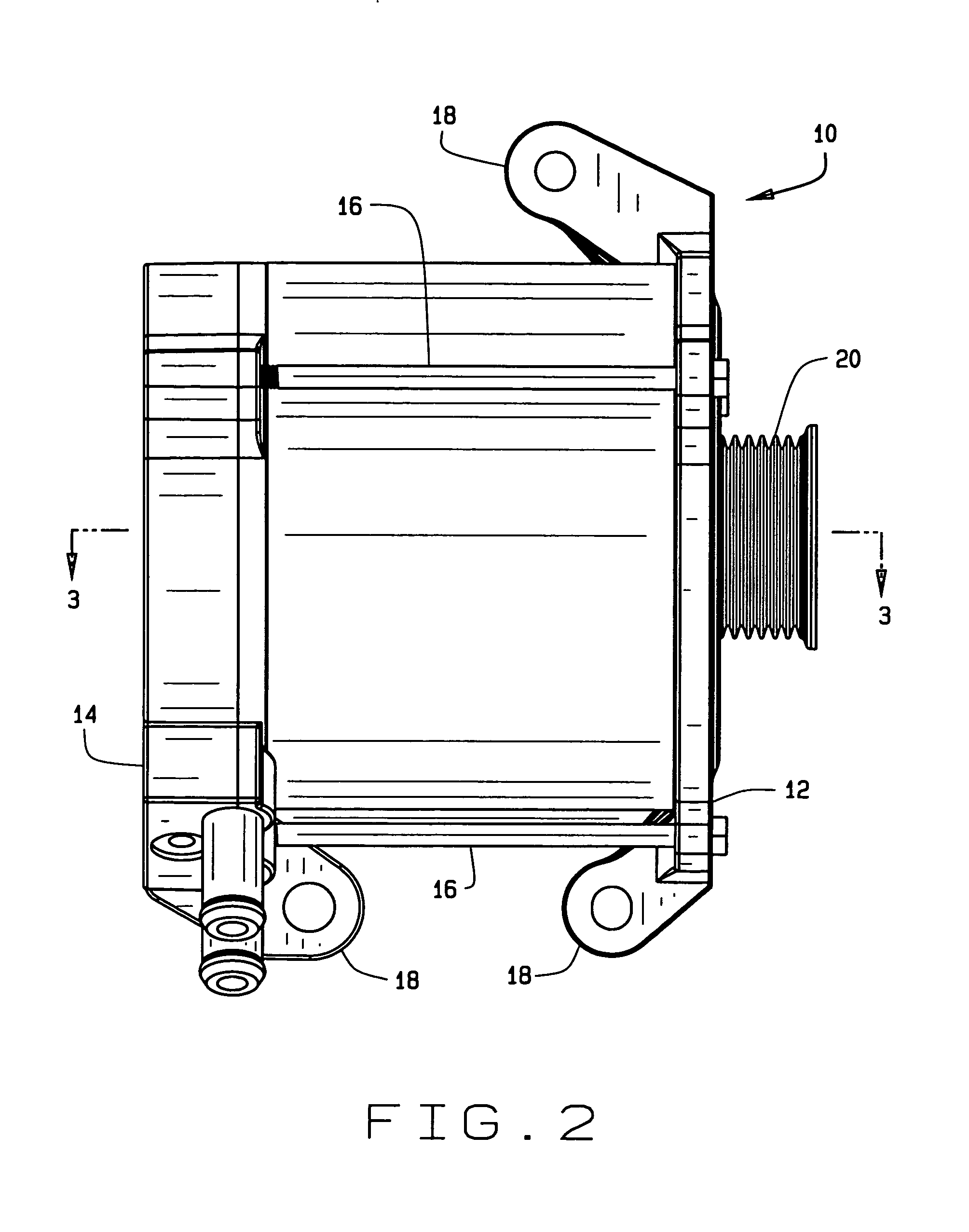
[0021] Referring now to the drawings and in particular to FIGS. 1-4, a dynamoelectric machine according to the present invention is designated in its entirety by the reference numeral 10. The machine 10 is particularly suited for use in applications where space constraints require the length of the machine to be smaller than would be desired for its expected output. In one embodiment, the machine is intended for installation into an engine compartment of an automotive vehicle for use as an integrated starter and generator. Although the description herein is primarily with reference to that embodiment, it is understood that other dynamoelectric machines, such as electric motors or generators of other sizes and for other fields of industry, do not depart from the scope of this invention.

[0022] A front endshield 12 (FIGS. 1-4) an...


PUM


Abstract

A compact dynamoelectric machine having a rotor with a length which is less than the length of a corresponding stator core. The rotor is rotatable on a shaft supported by bearings, with at least one of the bearings being positioned longitudinally within the stator core. Two endshields define opposite ends of the machine. One of the endshields is configured for holding electronic components in arrangement integrated with the machine.

Description

BACKGROUND OF THE INVENTION [0001] This invention relates generally to dynamoelectric machines, and in particular to an integrated starter generator having a rotor of decreased length to meet space constraints while maintaining efficient performance. [0002] Dynamoelectric machines such as electric motors convert energy between electrical current and mechanical motion. As known to those skilled in the art, a machine typically includes a rotatable assembly, or rotor, mounted within a hollow core of a stationary assembly, or stator, which holds windings of insulated wire. The windings are energized with electrical current, causing the stator to magnetically interact with the rotor. The rotor and stator have cross-sectional shapes and sizes configured to minimize radial spacing between rotor and stator (known as the air gap), while avoiding any direct physical contact which could interfere with free rotation of the rotor. [0003] Frequently, a machine must fit within a relatively small s...

Claims


Application Information

Patent Timeline
IPC IPC(8): H02K1/06H02K5/15H02K5/173H02K7/08H02K11/04H02K19/10H02K37/04
CPCH02K1/06H02K5/1732H02K19/103H02K11/048H02K7/083H02K7/08
Inventor MCCLELLAND, MICHAEL L.HORST, GARY E.
Owner NIDEC SR DRIVES
Why Eureka
Try Eureka