Integrable acoustic resonator and method for integrating such resonator

a technology of acoustic resonators and integrated resonators, which is applied in the direction of multiple resonant circuits tuned to the same frequency, single resonant circuits with varying inductance/capacitance only, continuous tuning, etc., can solve the problem of inability to eliminate the dispersion of electric characteristics of the resonator, use of acoustic resonators, etc. problem, to achieve the effect of strengthening the capacitive tuning

Active Publication Date: 2005-08-11
STMICROELECTRONICS SRL
View PDF6 Cites 2 Cited by
  • Summary
  • Abstract
  • Description
  • Claims
  • Application Information

AI Technical Summary

Benefits of technology

[0024] Thus, in both cases, the effect of the capacitive tuning element is strengthened by means of a judiciously selected inductive res...

Problems solved by technology

They are likely, however, to be useful in many other applications in the future but the principal obstacle to the use of acoustic resonators lies in the difficulty of integrating them into a semiconductor product.
Even with particularly ambitious and inevitably expensive specifications—for example, with a tolerance of about 1 percent for the dimensions of the resonator elements, dispersion on electric characteristics of the resonator cannot be eliminated.
This traditional approach cannot be chosen when aiming to integrate such an acoustic resonator on a substrate.
Indeed, in this case, discarding a great number of manufactured products only because part of the product—which only accounts ...

Method used


Image

  • Integrable acoustic resonator and method for integrating such resonator
  • Integrable acoustic resonator and method for integrating such resonator
  • Integrable acoustic resonator and method for integrating such resonator

Examples


first embodiment

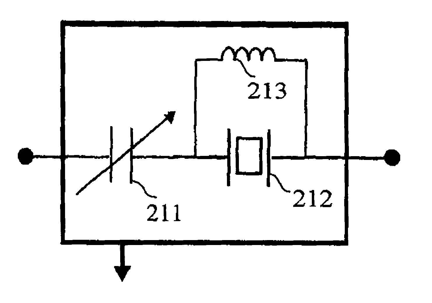
[0049]FIG. 2a illustrates the invention in which the series resonance the resonator is acted upon. To this end, a resonator 212 and an inductive resistor 213 that is calibrated to start resonating with the parallel capacity of this same resonator, close to frequency fp, are assembled in parallel connection. It is then possible to properly work on the series resonance and to compensate for its lack of precision (i.e., series frequency fs) by means of a capacitive tuning element 211.

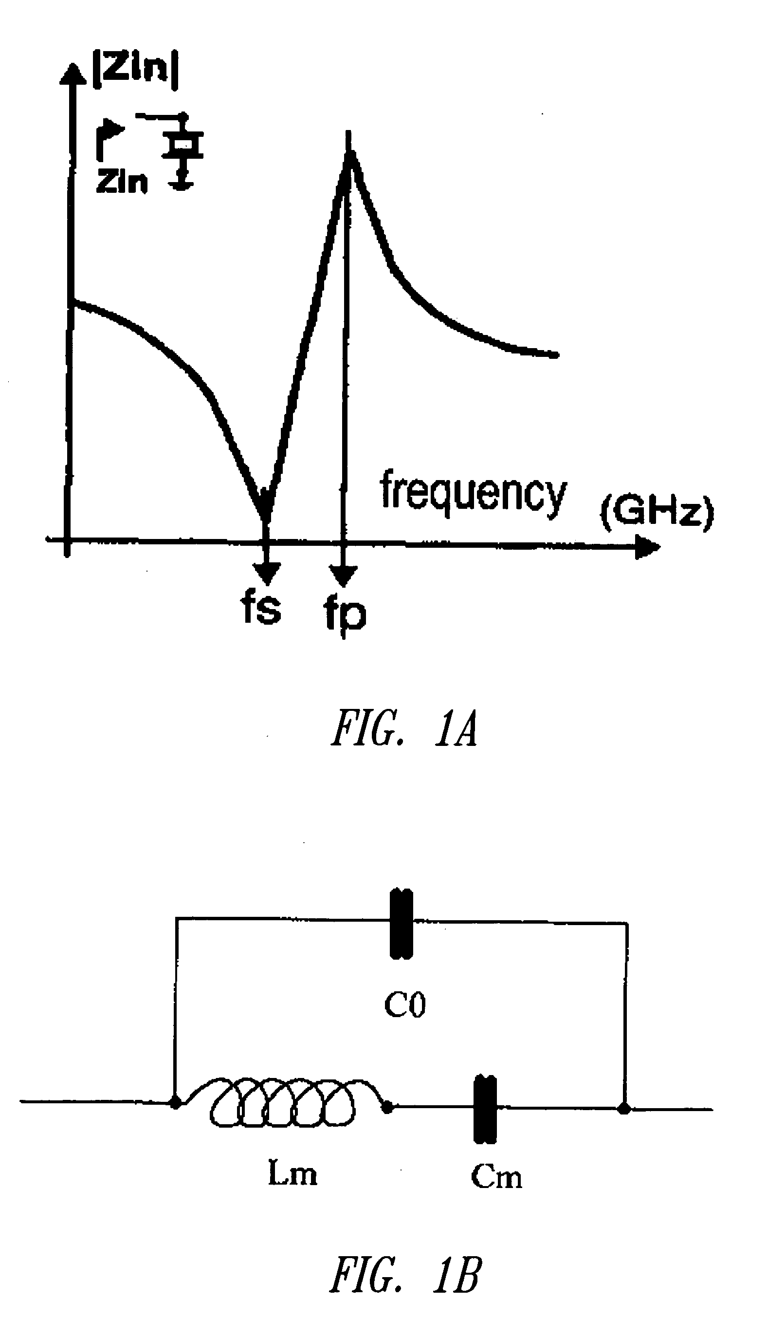
[0050] Referring to FIG. 1b, the inductance of inductive element 213 is given by:

L{circle over (×)}1 / (4π2)×1 / (C0×fp2)

second embodiment

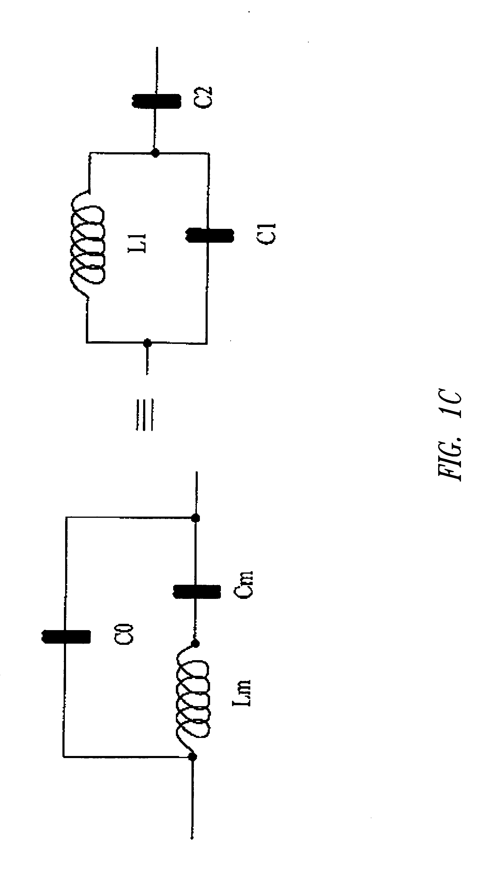
[0051]FIG. 2b corresponds to a second embodiment in which the parallel resonance of a resonator 222 is now acted upon. To this end, this time an inductive resistor 223 that is calibrated to start resonating with the equivalent series capacity (C2) close to frequency fs of the resonator of FIG. 1c is connected in series with resonator 222. Then, a capacitive tuning element (221) is connected in parallel with both series elements, to interact with the parallel resonance of resonator 222 and to regulate frequency fp.

[0052] Thus, one manages to adjust the operational frequency—within a broad range—by means of tuning element, 211 or 221 according to the case. There is a true cooperation between inductive resistor 213 (or 223) which interacts on the first of the two resonant frequencies so as to reinforce the capacitive tuning carried out by tuning element 211 (or 221).

[0053] An element for tuning the operation frequency, series or parallel according to the case, is thus obtained which m...


PUM


Abstract

An acoustic resonator circuit to be integrated into a semiconductor product including: a resonator comprising first and second resonant frequencies; an inductive resistor tuned to said second resonant frequency so as to cancel the latter and to allow tuning of the resonator to said first resonant frequency; an tunable capacitive tuning element allowing to tune the resonator to said first frequency. A method is also provided for manufacturing an integrated circuit comprising an acoustic component allowing sufficient control of resonator characteristics.

Description

BACKGROUND OF THE INVENTION [0001] 1. Field of the Invention [0002] The present disclosure generally relates to microelectronic circuits and more particularly but not exclusively to an acoustic resonator intended to be integrated into a semiconductor product. [0003] 2. Field of the Invention [0004] Acoustic resonators are well-known components that have been the subject of many studies. They are typically used for filtering operations, in particular in radio frequency (RF) filtering. [0005] Conventionally, one distinguishes between Surface Acoustic Resonator (SAW) and Bulk Acoustic Resonators (BAW). In SAWs, the acoustic resonator is located on the surface of a semiconductor product while, in RAWs, it lays inside a volume delimited between a lower electrode and a higher electrode so that the acoustic wave develops in this volume. [0006] Acoustic resonators are frequently used in RF filtering. They are likely, however, to be useful in many other applications in the future but the pri...

Claims


Application Information

Patent Timeline
IPC IPC(8): H03J3/18H03J3/20H03J3/24H03L5/00H03L7/00
CPCH03H2009/02204H03J3/185H03J3/20H03L7/0805H03J3/24H03L5/00H03L7/00H03J3/22
Inventor CARPENTIER, JEAN-FRANCOISTILHAC, CYRILLEBELOT, DIDIER
Owner STMICROELECTRONICS SRL
Why Eureka
Try Eureka