
Method and device for x-ray inspection of tire

Active Publication Date: 2005-08-11
BRIDGESTONE CORP
View PDF2 Cites 8 Cited by
  • Summary
  • Abstract
  • Description
  • Claims
  • Application Information

AI Technical Summary

Benefits of technology

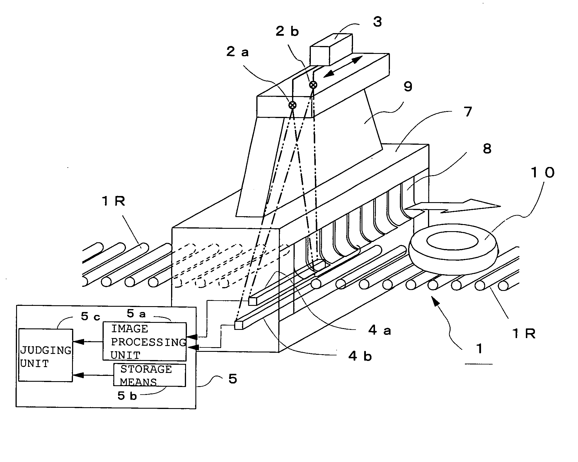
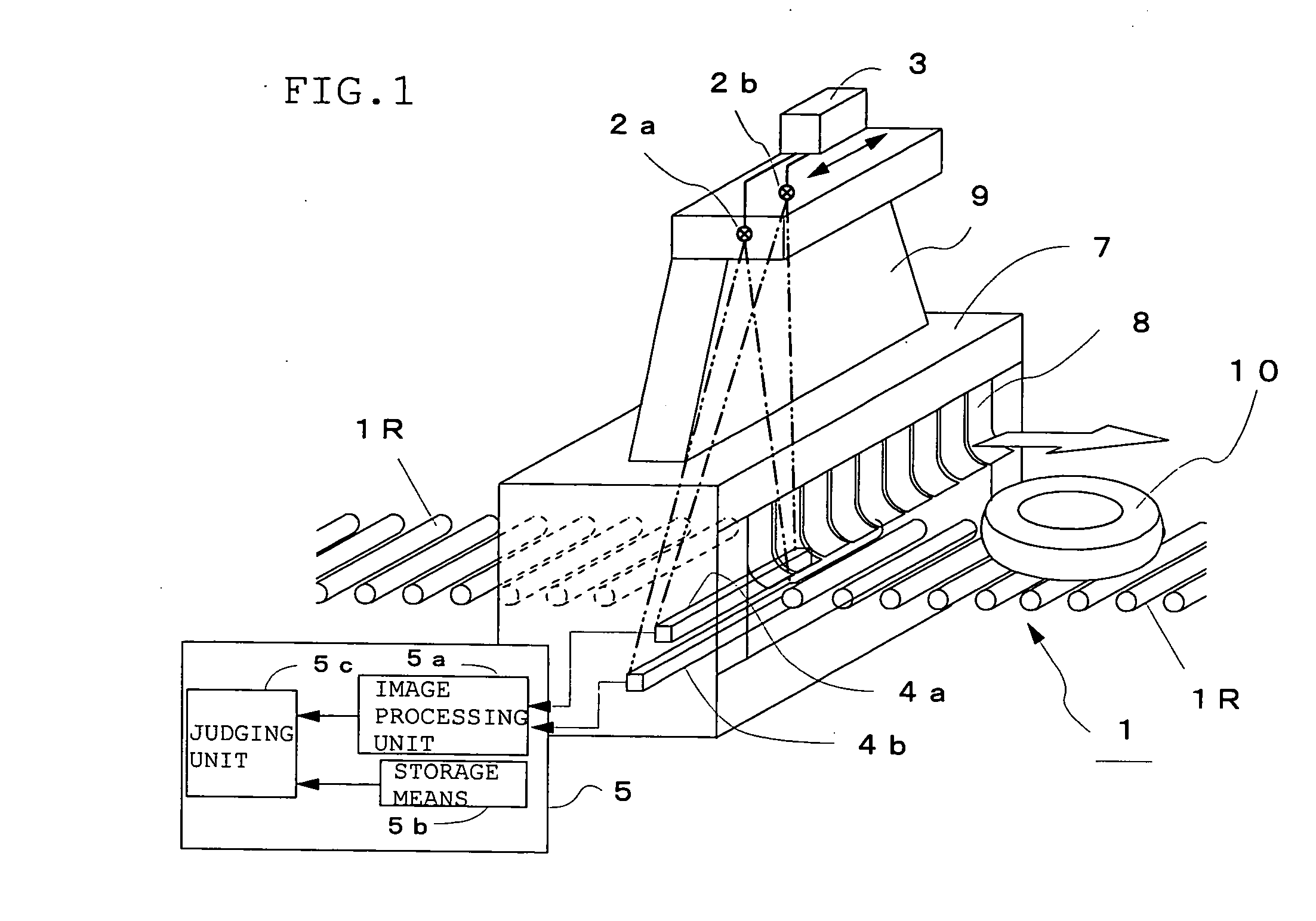
[0010] That is, according to a first aspect of the present invention, there is provided method of inspecting the interior of a tire from a transmission X-ray image of the tire obtained by applying an X-ray to the conveyed tire from X-ray application means, comprising the step of applying the X-ray to at least two positions including the opposite ends of the tires to take transmission X-ray images of the tire. Thereby, an x-ray image having few shadows of the bead wires and the tread belt can be obtained, thereby making it possible to inspect the interior of the tire accurately.
[0022] the X-ray application means are installed at positions corresponding to at least two positions including the opposite ends of the conveyed tire. Thus, by taking transmission X-ray images of the tire from at least two directions by using at least two X-ray application means, an image of the interior of the tire having the smallest dead area can be obtained, thereby making it possible to improve the accuracy of the internal inspection of the tire.
[0025] According to a ninth aspect of the present invention, there is provided an X-ray tier inspection apparatus, wherein the X-ray application means are installed at opposite positions right above the inner wall portion of the tread belt. This is aimed to minimize the influence of the tread belt which has the largest influence upon the dead area.
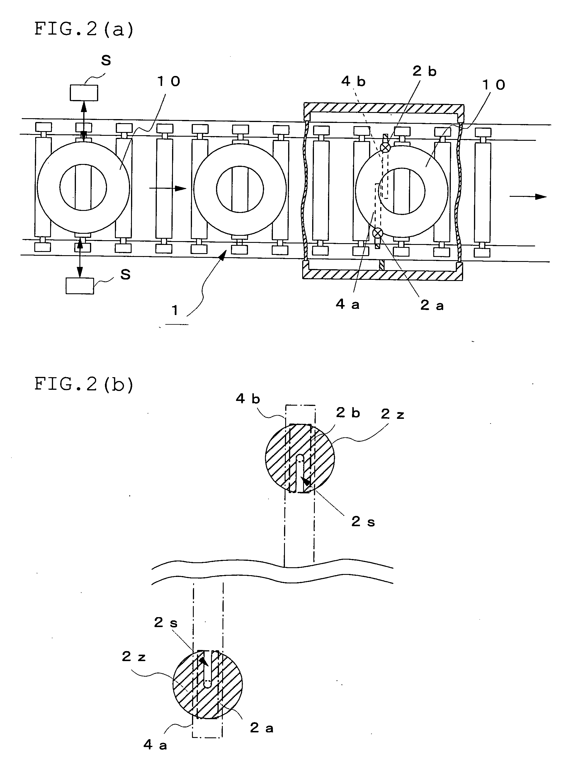
[0026] According to a tenth aspect of the present invention, there is provided an X-ray tire inspection apparatus, wherein one of the X-ray application means and an X-ray sensor for taking a transmission X-ray image of the tire with the X-ray application means are shifted from the other X-ray application means and the other X-ray sensor by a predetermined distance in the tire conveyance distance, respectively. Thereby, since the X-ray application ranges do not overlap with each other, more accurate transmission X-ray images of the tire can be obtained.
[0027] According to an eleventh aspect of the present invention, there is provided an X-ray tire inspection apparatus, wherein the X-ray sensors are X-ray line sensors and the X-ray application means are provided with a shielding plate having a slit extending in the internal direction of the tire from the center portion and parallel to the extending direction of the X-ray line sensor. Thereby, the X-ray application ranges can be minimized and the overlapping of the X-ray application ranges of the two X-ray application means can be prevented.
[0029] According to a thirteenth aspect of the present invention, there is provided an X-ray tire inspection apparatus, wherein the interval between the two X-ray application means can be changed. Thereby, the internal inspection of various tires which differ in size can be made possible easily.

Problems solved by technology

In this method in which tires are take out one by one, the production line must be suspended each time inspection is made, thereby reducing productivity.
However, as inspection takes too long in this method, it cannot be said that this method is practical.

Method used


Image

  • Method and device for x-ray inspection of tire
  • Method and device for x-ray inspection of tire
  • Method and device for x-ray inspection of tire

Examples


example

[0057] As shown in FIGS. 5(a) and 5(b), 12 test pieces 20 formed by sandwiching four metal washers 21 arranged in a row at equal intervals between two acrylic boards 22 and 22 were arranged symmetrical about the center of a tire 10Z on the side surface of the tire (215 / 50 ZR17) having an aspect ratio of 50(%) and a transmission X-ray image of this tire 10Z was taken by the X-ray inspection apparatus of the present invention and shown in FIG. 6(a). A transmission X-ray image of the same tire Z taken by an X-ray inspection apparatus having only one X-ray source of the prior art is shown in FIG. 6(b). As obvious from comparison between FIGS. 6(a) and 6(b), since the dead area formed by the tread belt 12 is large in the apparatus of the prior art, only one out of the four washers 21 can be detected. In contrast to this, in the apparatus of the present invention, all the four washers 21 can be detected. Therefore, it is confirmed that the dead area becomes extremely small in the transmis...


PUM


Abstract

An X-ray tire inspection apparatus comprising X-ray tubes 2a and 2b for applying an X-ray to a tire 10, installed right above the opposite ends of the tire 10 conveyed by a roll conveyor 1, and X-ray line sensors 4a and 4b arranged in the space between adjacent rolls 1R and 1R below the above roll conveyor 1 at positions corresponding to the above X-ray tubes 2a and 2b, respectively, wherein transmission X-ray images of left half and right half portions of the tire 10 are taken by the X-ray line sensors 4a and 4b and combined by tire internal image inspection means 5 to obtain a transmission X-ray composite image of the whole tire 10. Therefore, even a tire having a low aspect ratio can be internally inspected accurately and efficiently.

Description

BACKGROUND OF THE INVENTION [0001] 1. Field of the Invention [0002] The present invention relates to a method of inspecting the interior of a tire with an X-ray and an apparatus used in the method. [0003] 2. Description of the Prior Art [0004] Heretofore, for tire internal inspection, a tire has been taken out from the line, a transmission X-ray image of the tire has been taken by an X-ray camera, and the states of bead wires as tire constituent members and the entry of foreign matter such as a micro-metal or small stone into the tire have been visually checked from the obtained transmission X-ray image of the tire by an operator to judge whether the tire is acceptable or not. In this method in which tires are take out one by one, the production line must be suspended each time inspection is made, thereby reducing productivity. Therefore, the tire internal inspection has to be sampling inspection. In addition, since the work of judging whether a tire is acceptable or not is carried ...

Claims


Application Information

Patent Timeline
IPC IPC(8): G01M17/03G01N23/04
CPCG01N23/04G01M17/028
Inventor UCHIDA, NORIMICHIKOKUBU, TAKAO
Owner BRIDGESTONE CORP
Learn More