Eureka AIR delivers breakthrough ideas for toughest innovation challenges, trusted by R&D personnel around the world.

Developing apparatus

Inactive Publication Date: 2005-08-11
SHARP KK
View PDF3 Cites 2 Cited by
  • Summary
  • Abstract
  • Description
  • Claims
  • Application Information

AI Technical Summary

Benefits of technology

[0009] The present invention was made to solve the foregoing problems. An object of the present invention is to provide a developer amount controlling blade that is free, even after prolonged use, from image deterioration caused by melt and adhesion of toner, and therefore has a long life.
[0015] According to the present invention, the developer amount controlling blade has, at least in a region that contacts the toner, a composite plated film containing fine particles of fluorocarbon resin and having excellent toner releasability. By optimizing the thickness of the film, the size of the fine particles, and the volume percentage of the fine particles of resin contained, the effect of the composite plated film can be maximized. This prevents melt and adhesion of the toner to the surface of the blade for a long time. Therefore, it is possible to provide a developing apparatus having high image quality and long life.

Problems solved by technology

This causes the problem that, after a long period of time, the toner melts and adheres to the developer amount controlling blade, due to friction and impression stress.
Under such a circumstance, melt and adhesion of the toner is accelerated, and deterioration of images (e.g. appearance of white lines) is more likely to occur.
However, in the developer amount controlling blade having the silicone or fluorocarbon resin layer, the amount of charge and the polarity of charge of the toner particles easily become uneven.
If the developer amount controlling blade having the silicone or fluorocarbon resin layer is pressed against the developer supporting body at a high contact pressure, the resin layer could be worn or peeled off after a prolonged use.
There are cases where, in the plated layer in which the fine particles of fluorocarbon resin are dispersed, the plated layer and the fine particles of fluorocarbon resin are peeled off or separated depending on the thickness of the plated layer, the amount of the plated layer, or the size of the fine particles of resin, for example, thereby making it impossible to attain desired effects in terms of toner releasability and a resistance property to melt and adhesion of toner.

Method used


Image

  • Developing apparatus
  • Developing apparatus
  • Developing apparatus

Examples


examples

[0067] The following specifically describes results of image formation performed by using the developer amount controlling blade.

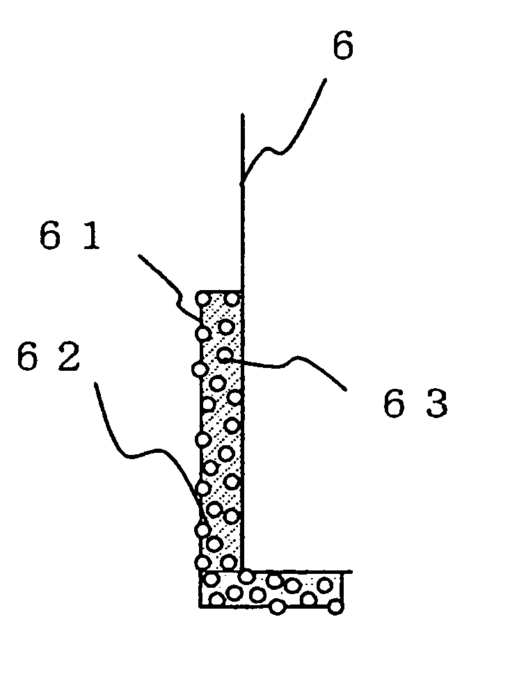
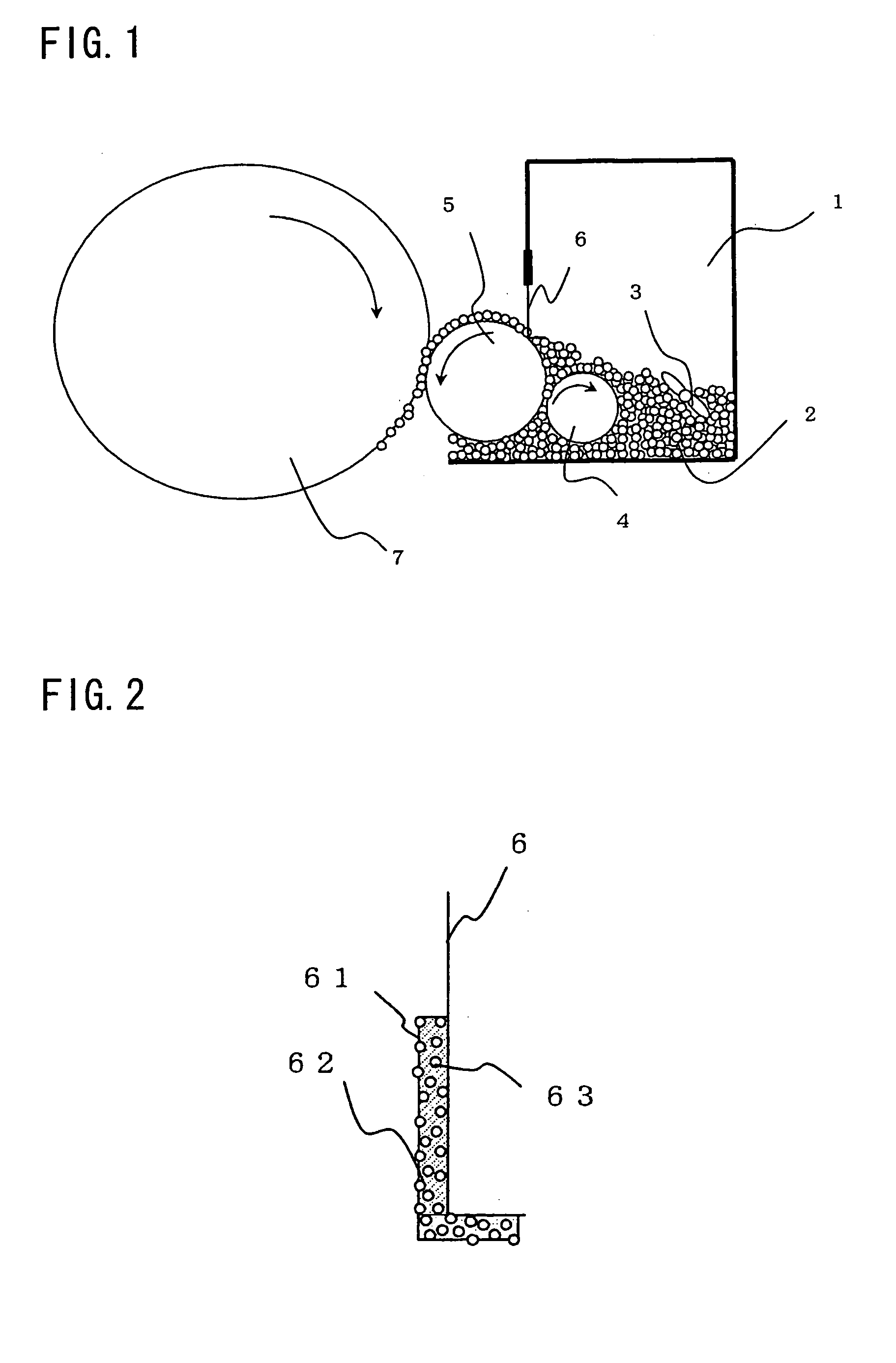
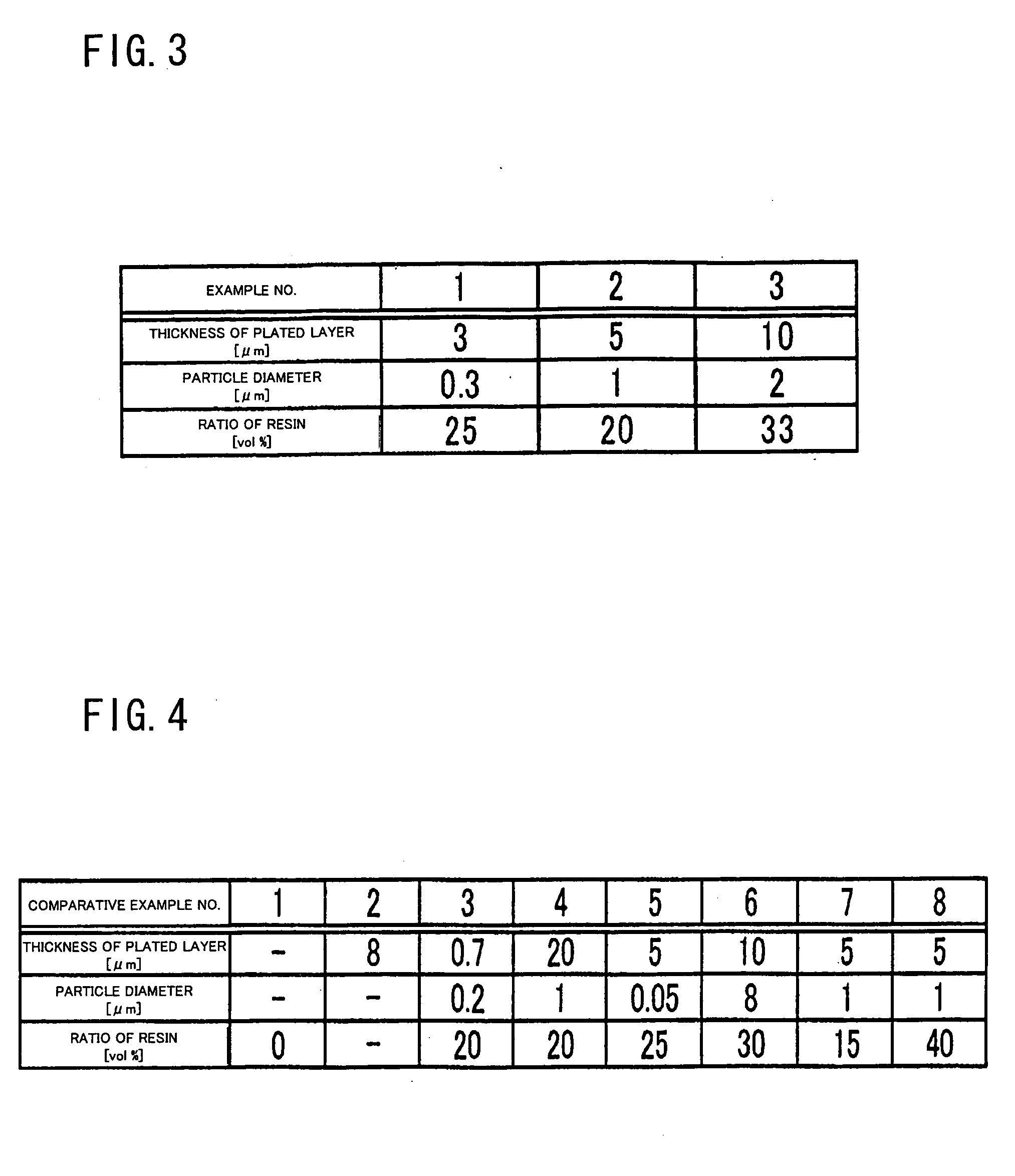
[0068] First, an example of a procedure for manufacturing the developer amount controlling blade is described. Using SUS304 (a product of Sohbi Kohgei Co., Ltd.) as a material of the blade member, punching was performed. In order to form a toner layer stably, a portion within 2 mm from the tip was bent into an L-shape. Then, a compound plated film containing fine particles of PTFE resin was formed by eutectoid. Conditions of the blade member used in EXAMPLES are shown in FIG. 3, and conditions of the blade member used in COMPARATIVE EXAMPLES are shown in FIG. 4. In EXAMPLE 2, heat processing was performed at 300° C. for one hour. In COMPARATIVE EXAMPLE 1, a SUS-only blade was used. In COMPARATIVE EXAMPLE 2, a PTFE resin film having a thickness of 8 μm was formed.

[0069] Then, with respect to the blades of EXAMPLES 1 to 3 and COMPARATIVE EXAMPLES 1 to 8, h...


PUM

PropertyMeasurementUnit
Lengthaaaaaaaaaa
Lengthaaaaaaaaaa
Lengthaaaaaaaaaa

Abstract

A developing apparatus includes a container for containing developer including toner; a developer supporting body, which is elastic and provided so as to contact an image supporting body, for supplying the developer to the image supporting body; and a developer amount controlling blade, which is attached to the container so as to contact the developer supporting body, for controlling an amount of toner supplied. The developer amount controlling blade has, at least in a region that contacts the toner, a composite plated film containing fine particles of fluorocarbon resin. It is preferable that the composite plated film is not thinner than 1 μm and not thicker than 15 μm. With this arrangement, it is possible to provide a developer amount controlling blade that is free, even after prolonged use, from image deterioration caused by melt and adhesion of the toner, and therefore has a long life.

Description

[0001] This nonprovisional application claims priority under 35 U.S.C. § 119(a) on Patent Application No. 032335 / 2004 filed in Japan on Feb. 9, 2004, the entire contents of which are hereby incorporated by reference. FIELD OF THE INVENTION [0002] The present invention relates to a developing apparatus used in electrophotographic image formation for developing and visualizing a latent image formed on an image supporting body, and relates in particular to a developing apparatus including a blade member for controlling the amount of developer. BACKGROUND OF THE INVENTION [0003] One of the conventionally known development methods using an electrophotographic process is impression development. The impression development is advantageous in many respects. For example, a developing apparatus using the impression development can be simplified and miniaturized easily, and can easily have high resolution. In this developing method, it is necessary to form a thin layer of developer on a develop...

Claims


Application Information

Patent Timeline
IPC IPC(8): C25D7/00G03G9/08C25D15/00G03G15/06G03G15/08
CPCG03G2215/0634G03G15/0812
Inventor AOKI, MOMOMI
Owner SHARP KK
Why Eureka
Eureka Blog
Learn More