Work-space pressure regulator

Active Publication Date: 2005-08-11
NEW POWER CONCEPTS
View PDF52 Cites 3 Cited by
  • Summary
  • Abstract
  • Description
  • Claims
  • Application Information

AI Technical Summary

Benefits of technology

[0005] In embodiments of the present invention, a device is provided that reduces the mean pressure difference between a work-space and a pressurized engine crankcase of an engine, such as a Stirling engine. The device includes a valve connecting the work-space and crankcase of the engine. The pressure difference between work-space and crankcase is monitored. When the mean pressure o

Problems solved by technology

In summary, pumping up the workspace mean pressure significantly increas

Method used


Image

  • Work-space pressure regulator
  • Work-space pressure regulator
  • Work-space pressure regulator

Examples


Example

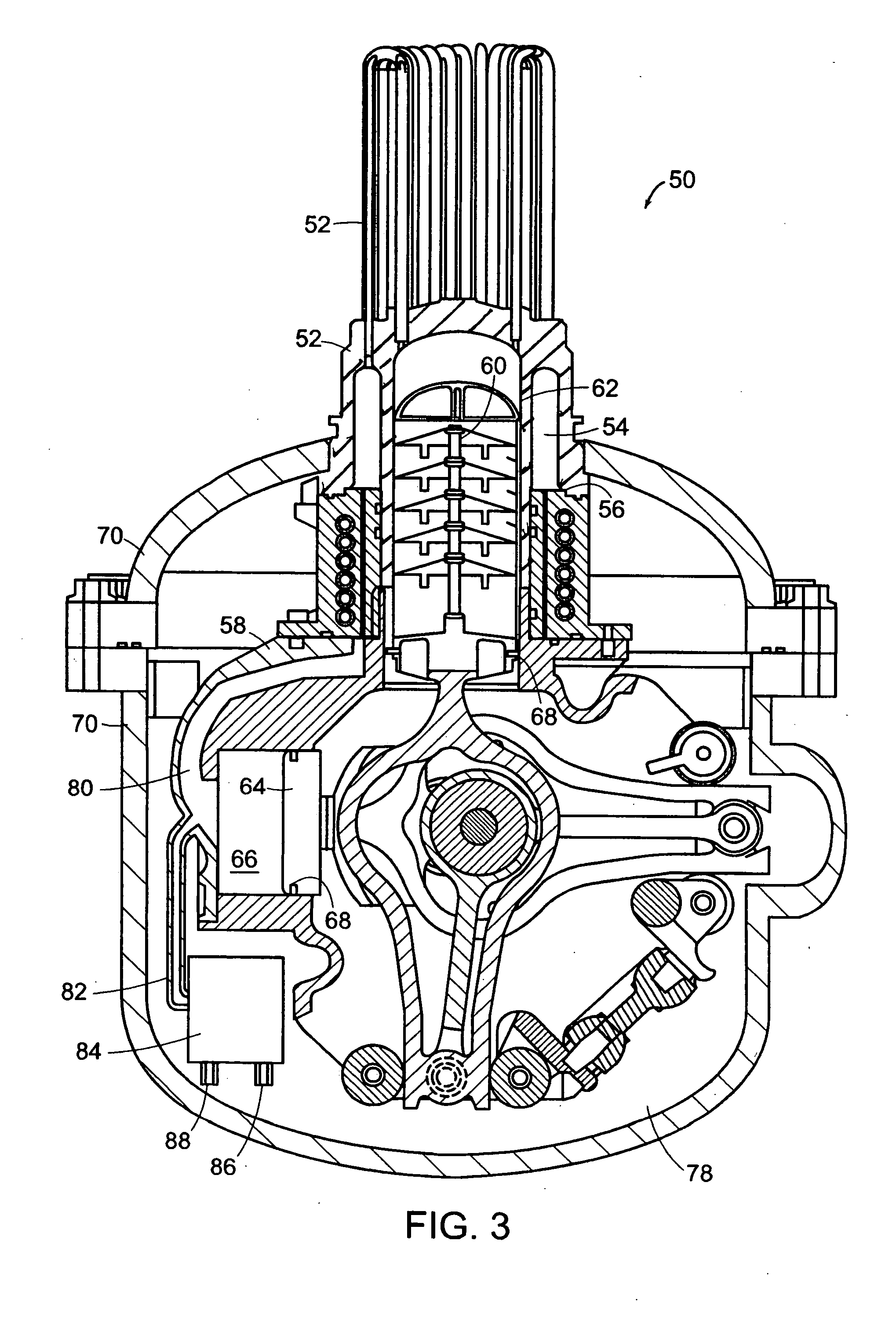
[0015] In embodiments of the present invention, a device is provided that reduces the pressure difference between a work-space and a pressurized engine crankcase of an engine, such as a Stirling engine. Referring to FIG. 3, a sealed Stirling cycle engine 50 is shown in cross section. While this embodiment of the present invention will be described with reference to the Stirling engine shown in FIG. 3, it should be understood that other engines, coolers, and similar machines may likewise benefit from embodiments of the present invention and such combinations are within the scope of the invention, as described in the appended claims. A sealed Stirling cycle engine operates under pressurized conditions. Stirling engine 50 contains a high-pressure working fluid, preferably helium, nitrogen or a mixture of gases at 20 to 140 atmospheres pressure. Typically, a crankcase 70 encloses and shields the moving portions of the engine as well as maintains the pressurized conditions under which th...


PUM


Abstract

A device and method for equalizing the pressure between work-space and crankcase in a pressurized engine, such as a Stirling engine. The device consists of a two-way valve connected between the work-space and the crankcase. The valve is connected to the work-space with a passageway including a constriction to provide an mean pressure for monitoring purposes. The valve connects the work-space and crankcase allowing the pressure to equalize when the mean pressure of the work-space exceeds the crankcase pressure by a predetermined amount.

Description

TECHNICAL FIELD [0001] The present invention pertains to regulating the pressure in the work-space of a pressurized engine, such as a Stirling engine. BACKGROUND OF THE INVENTION [0002] Stirling cycle machines, including engines and refrigerators, have a long technological heritage, described in detail in Walker, Stirling Engines, Oxford University Press (1980), and incorporated herein by reference. The principle underlying the Stirling cycle engine is the mechanical realization of the Stirling thermodynamic cycle: isovolumetric heating of a gas within a cylinder, isothermal expansion of the gas (during which work is performed by driving a piston), isovolumetric cooling, and isothermal compression. [0003] A Stirling cycle engine operates under pressurized conditions. Stirling engines contain a high-pressure working fluid, preferably helium, nitrogen or a mixture of gases at 20 to 140 atmospheres pressure. A Stirling engine may contain two separate volumes of gases, a working gas vol...

Claims


Application Information

Patent Timeline
IPC IPC(8): F04B49/08
CPCF04B49/08
Inventor GURSKI, THOMAS Q.LANGENFELD, CHRISTOPHER C.SMITH, STANLEY B. III
Owner NEW POWER CONCEPTS
Why Eureka
Try Eureka