Ocean wave energy converter having an improved generator and ballast control

Active Publication Date: 2005-12-29
AMES P FOERD
View PDF99 Cites 35 Cited by
  • Summary
  • Abstract
  • Description
  • Claims
  • Application Information

AI Technical Summary

Benefits of technology

[0008] Accordingly, among the objects of the present invention is the provision for an ocean wave energy converter that maximizes upstroke power generation.
[0009] Another object of the presen

Problems solved by technology

Namely, the use of many permanent magnets made the design costly.
Moreover, not all the permanent magnets were being used to their optimal capacity resulting in its inefficient use.
A design that attempts to maximize both peak and troth power generation s

Method used


Image

  • Ocean wave energy converter having an improved generator and ballast control
  • Ocean wave energy converter having an improved generator and ballast control
  • Ocean wave energy converter having an improved generator and ballast control

Examples


Example

[0035] In yet a third embodiment (not shown), a stationary coil is secured adjacent to the outer rotor 64 of the generator 26.

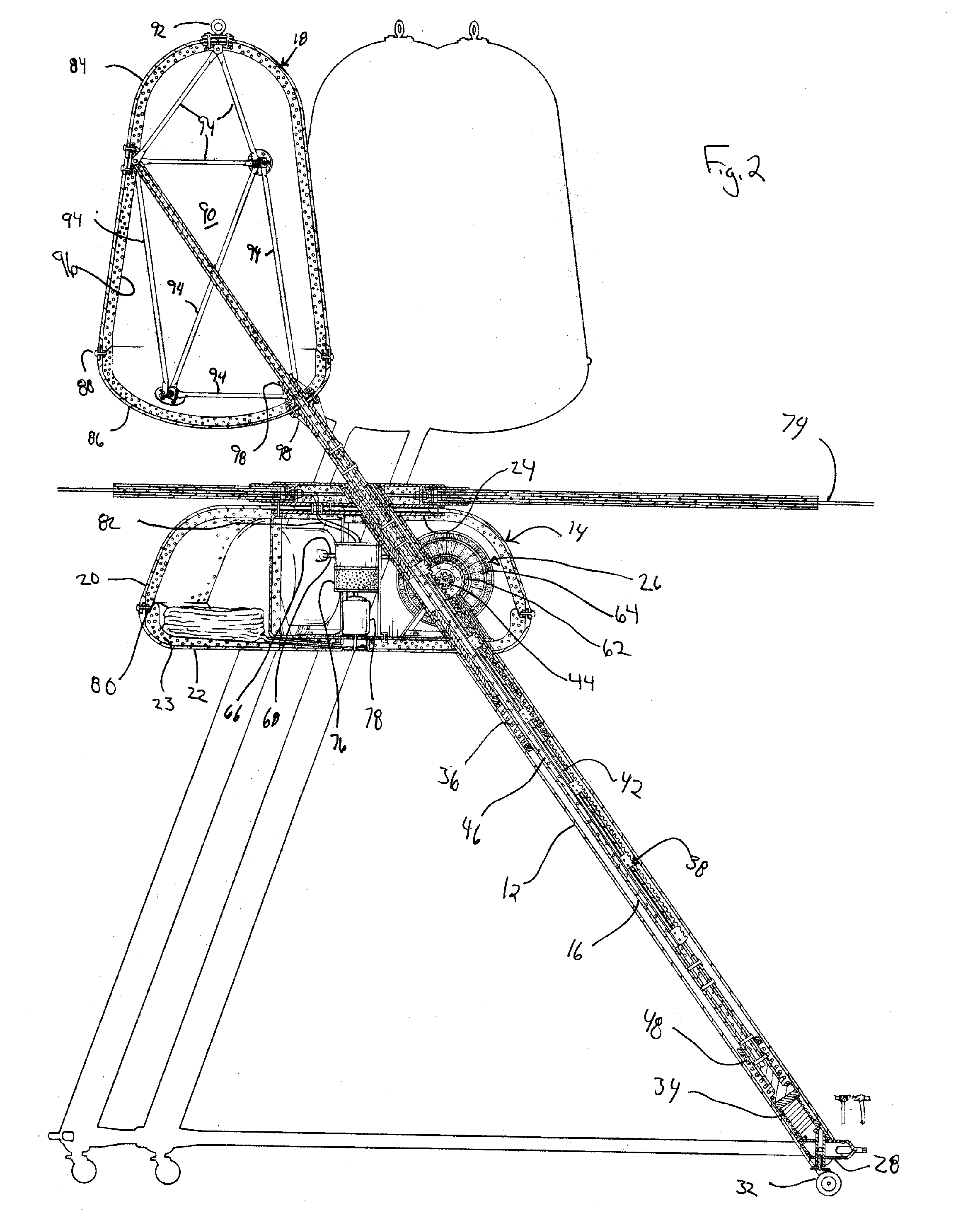
[0036] Referring back to FIG. 2, the inner cavity of the main body member 14 also includes an active ballast control system that includes a desiccant 76, a pump 78, and three bladders 80 that are secured to the chassis 24. The desiccant 76 measures the attitude and depth to the OWEC assembly 10 relative to mean sea level and generates control inputs to the pump 78 to keep the OWEC assembly 10 at an optimum depth in the water. The pump 78 fills or evacuates the bladders 80 according to the inputs received from the desiccant 76. The bladders 80 are fashioned of a non-porous flexible material that is easily deformed. The pump 78 and desiccant 76 are connected by wires 82 to the umbilical chord 74 and are powered from excess electrical power generated by the generators 26, but also could be easily supplemented from other optional power sources such as an additio...


PUM


Abstract

The ocean wave energy converter uniquely includes a generator with a rotating inner rotor surrounded by a counter-rotating outer rotor for generating electricity. A reciprocating drive rod drives the inner rotor on the downstroke of the drive rod and the outer rotor on the upstroke of the drive rod through a gear driven driveshaft with clutches. A buoy is attached to end of the drive rod whereby the undulation of the ocean waves relative to the buoy reciprocates the drive rod between the upstroke and the downstroke positions.

Description

CROSS-REFERENCE TO RELATED APPLICATION [0001] This application claims priority to earlier filed U.S. Provisional Patent Application Ser. No. 60 / 583,374 filed Jun. 28, 2004, the contents of which are incorporated herein by reference.BACKGROUND OF THE INVENTION [0002] 1. Field of the Invention [0003] The present invention generally relates to an apparatus for converting the energy of wave motion on the surface of a body of water to electricity. The assembly is designed as an ocean wave energy converter module that can be interconnected to other modules to form an ocean wave energy web. [0004] 2. Background of the Related Art [0005] Ames, U.S. Pat. No. 4,232,230 describes an ocean wave energy converter module having several linear reciprocating electric generators, which are assembled in a generally pyramidal or conical form. Their movable armature members are connected to floats (buoys) above the apex which are adapted to follow displacements of the water surface. The lower ends of th...

Claims


Application Information

Patent Timeline
IPC IPC(8): F03B13/10F03B13/12F03B13/18H02P9/04
CPCF03B13/12F03B13/186Y02E10/38F05B2240/40F03B13/1885Y02E10/30
Inventor AMES, P. FOERD
Owner AMES P FOERD
Why Eureka
Try Eureka