
Linear compressor

Inactive Publication Date: 2005-08-11
LG ELECTRONICS INC
View PDF11 Cites 68 Cited by
  • Summary
  • Abstract
  • Description
  • Claims
  • Application Information

AI Technical Summary

Benefits of technology

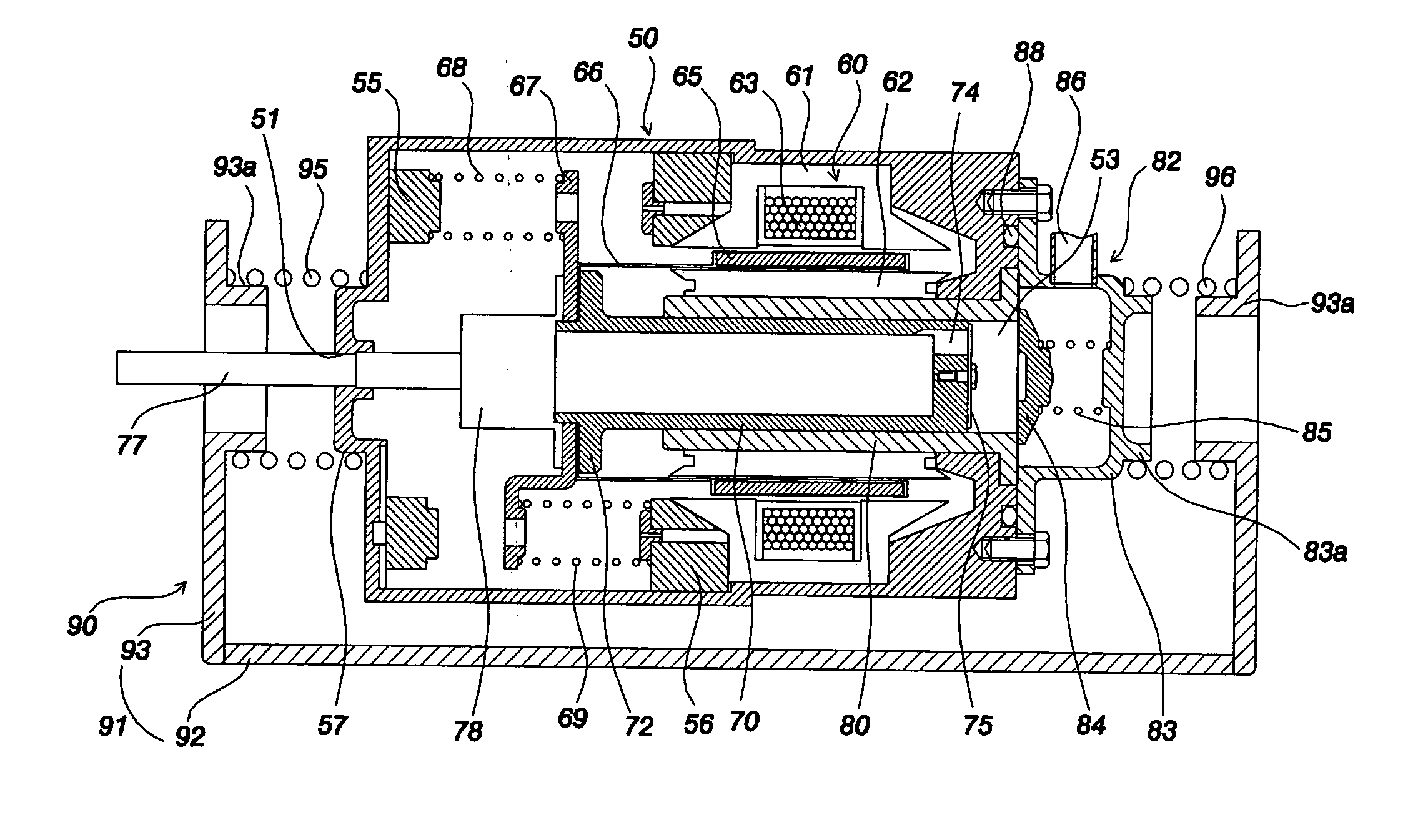
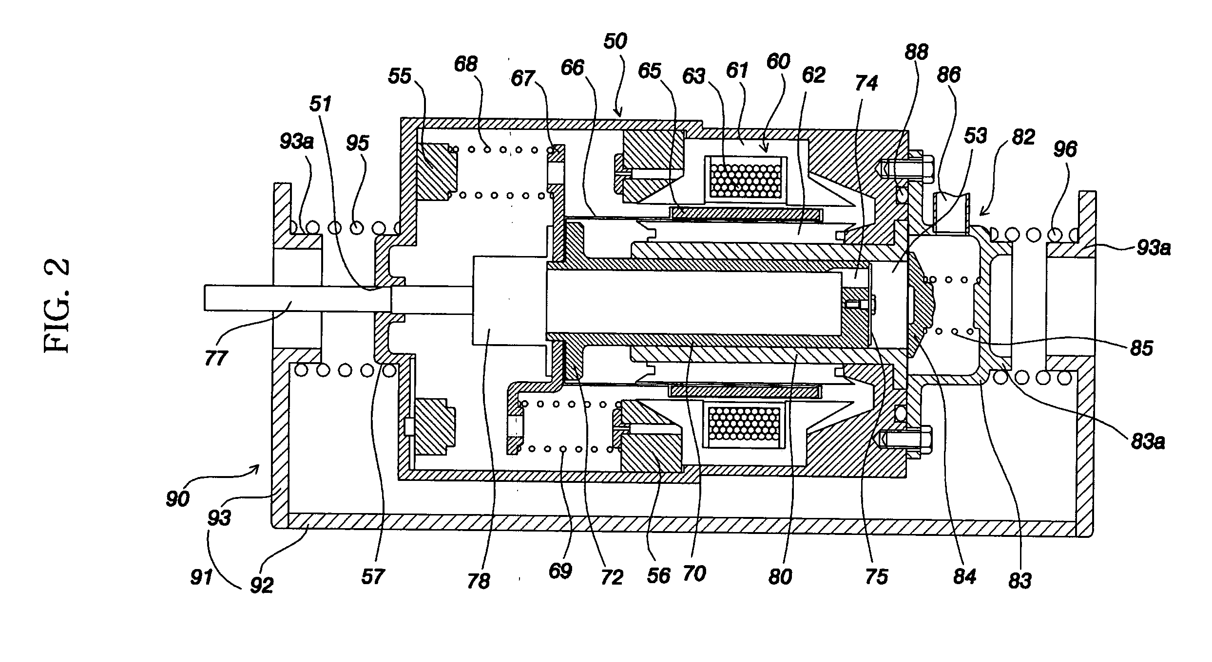
[0018] Therefore, the present invention has been made in view of the above problems, and it is an object of the present invention to provide a linear compressor wherein a discharging unit and vibration-absorbing components are disposed outside a hermetically sealed container to reduce the size of the hermetically sealed container, whereby the linear compressor is miniaturized, and the linear compressor is designed without limits.
[0026] Preferably, the linear compressor further comprises: a silencer disposed at the rear of the piston for reducing inlet noise.
[0030] In the linear compressor according to the present invention, the discharging unit assembly and the shock-absorbing support unit are disposed at the outside of the hermetically sealed container to reduce the size of the hermetically sealed container. Consequently, the present invention has the effect that the linear compressor is miniaturized, and the linear compressor is designed without limits.
[0031] According to the supporting structure of the hermetically sealed container according to the present invention, vibrations generated in the direction in which the linear motor is operated and vibrations generated in the radial and rotating directions of the hermetically sealed container are effectively absorbed. Consequently, the present invention has the effect of supporting the hermetically sealed container while absorbing shocks applied to hermetically sealed container.

Problems solved by technology

As a result, it is difficult to miniaturize the linear compressor, and thus the linear compressor is designed within the limits.

Method used


Image

  • Linear compressor
  • Linear compressor
  • Linear compressor

Examples


Embodiment Construction

[0039] Now, preferred embodiments of the present invention will be described in detail with reference to the accompanying drawings.

[0040] It should be understood that linear compressors according to numerous preferred embodiments of the present invention may be proposed, although only the most preferred embodiments of the present invention will be hereinafter described.

[0041]FIG. 2 is a longitudinal sectional view showing a linear compressor according to a preferred embodiment of the present invention.

[0042] As shown in FIG. 2, the linear compressor according to the present invention includes: a hermetically sealed container 50 having an inlet port 51 and an outlet port 53 formed therein; a linear motor 60 fixed to the inside of the hermetically sealed container 50 for generating a linear moving force; a cylinder 80 fixed to the inside of the hermetically sealed container 50 adjacent to the outlet port 53; a discharging unit assembly 82 disposed in front of the outlet port 53 at ...


PUM


Abstract

Disclosed herein is a linear compressor. The linear compressor comprises a hermetically sealed container having an inlet port and an outlet port formed at both ends thereof. In the hermetically sealed container is mounted a compression unit to compress and discharge a fluid. The compression unit comprises a linear motor, a cylinder, and a piston disposed in the cylinder such that the piston is linearly reciprocated in the cylinder by means of the linear motor. The linear compressor further comprises a discharging unit assembly disposed in front of the outlet port at the outside of the hermetically sealed container such that a fluid compressed in the cylinder is discharged through the discharging unit assembly, a container-supporting stand to support the hermetically sealed container at the outside of the hermetically sealed container, and shock-absorbing springs disposed between the container-supporting stand and the hermetically sealed container for performing shock-absorbing operations. According to the present invention, the size of the hermetically sealed container is reduced, whereby the linear compressor is miniaturized, and thus the linear compressor is designed without limits.

Description

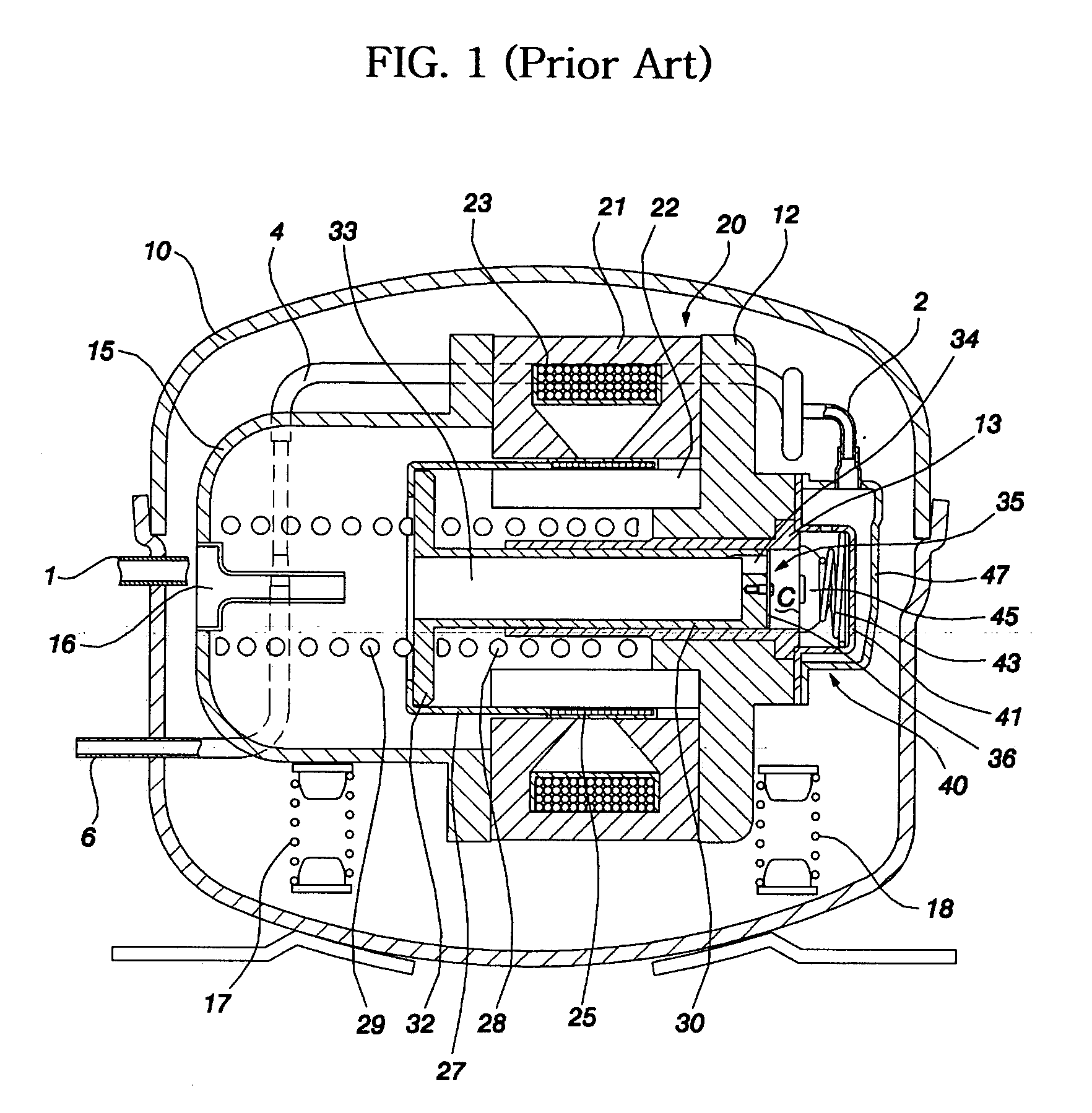
BACKGROUND OF THE INVENTION [0001] 1. Field of the Invention [0002] The present invention relates to a linear compressor, and more particularly to a linear compressor wherein specific components are disposed outside a hermetically sealed container so as to reduce the size of the hermetically sealed container, whereby a linear compressor is miniaturized. [0003] 2. Description of the Related Art [0004] Generally, a linear compressor is constructed such that a linear driving force from a linear motor is transmitted to a piston, which is linearly reciprocated in a cylinder, whereby a fluid is introduced, compressed, and discharged. [0005]FIG. 1 is a longitudinal sectional view showing a conventional linear compressor. As shown in FIG. 1, the conventional linear compressor comprises a cylinder block 12 and a back cover 15 mounted inside a hermetically sealed container 10. The cylinder block 12 has a cylinder 13 formed therein, and the back cover 15 has a fluid inlet port 16 formed therei...

Claims


Application Information

Patent Timeline
IPC IPC(8): F04B35/04F04B39/12F04B17/04
CPCF04B35/045F04B39/127F04B39/121F04B39/0044F16F15/067F16F15/08F16J15/02F05B2210/14F05B2210/12F05B2260/96F05B2240/57
Inventor PARK, JONG JINPARK, JOON WOO
Owner LG ELECTRONICS INC
Learn More