Press-fit terminal

Active Publication Date: 2005-08-11
AUTONETWORKS TECH LTD +2
View PDF20 Cites 51 Cited by
  • Summary
  • Abstract
  • Description
  • Claims
  • Application Information

AI Technical Summary

Benefits of technology

[0017] In this arrangement, the effect of the hardness of the diffus

Problems solved by technology

A press-fit terminal plated with tin has an excellent reliability in connection to the electrically-conductive through-hole in the board but is disadvantageous in that the tin deposit can be scraped during

Method used


Image

  • Press-fit terminal
  • Press-fit terminal
  • Press-fit terminal

Examples


Embodiment Construction

[0022] Embodiments of implementation of the invention will be described in detail in connection with the attached drawings.

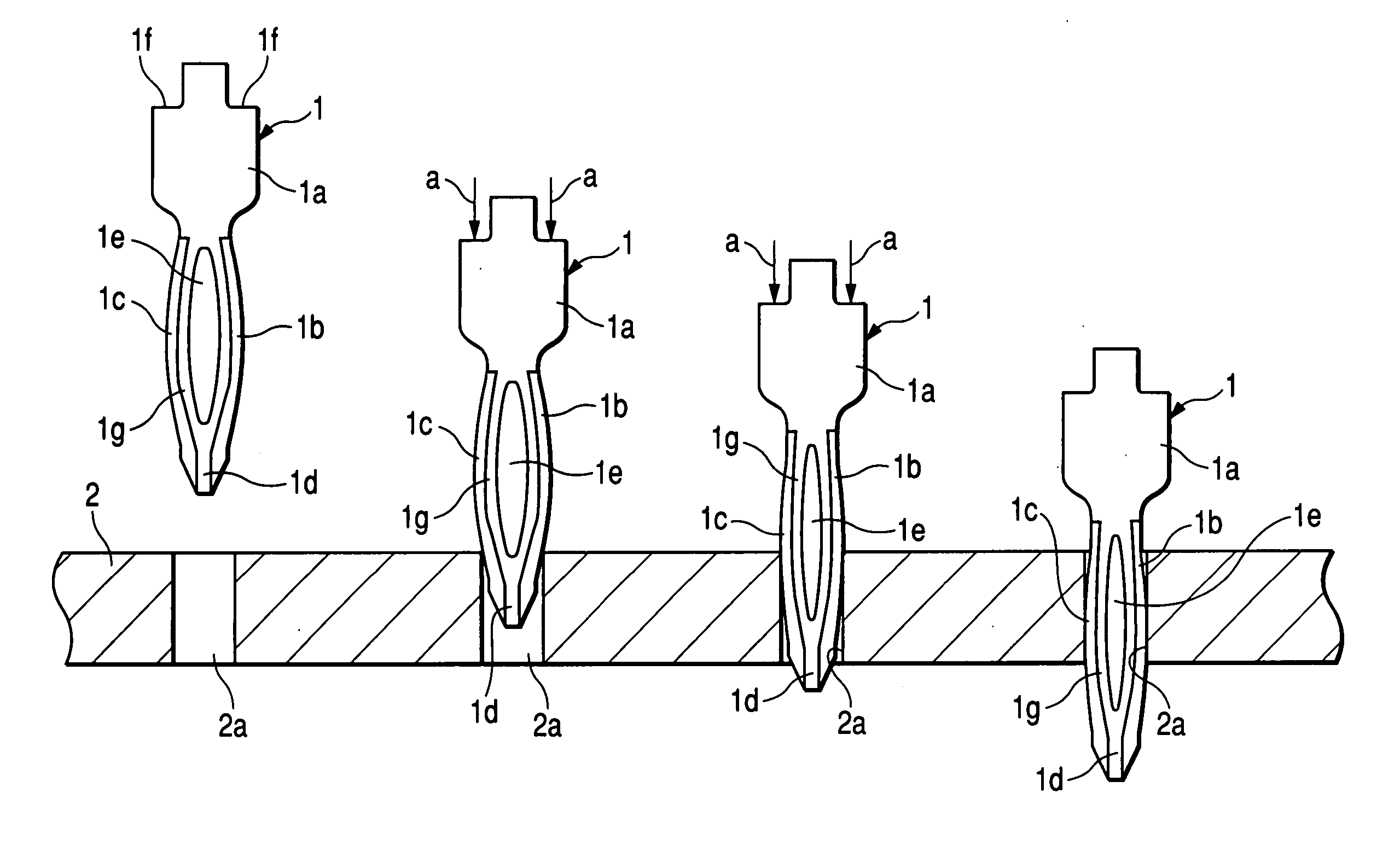
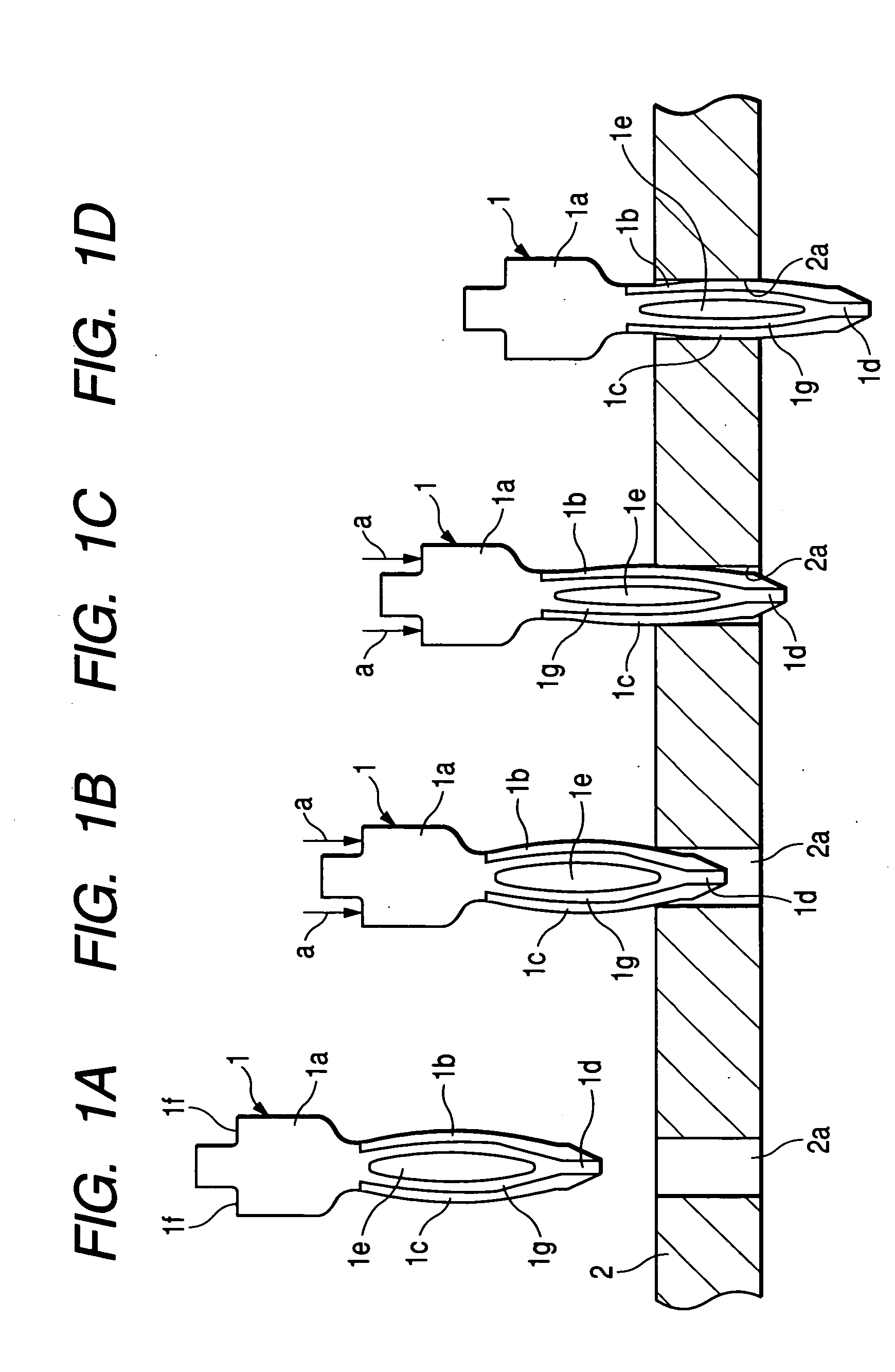
[0023] As shown in FIG. 1A, the press-fit terminal 1 has a terminal base portion 1a and a board inserting portion 1b provided therein. On the board inserting portion 1b are formed a forward end inserting portion 1d piercing a through-hole 2a in a board 2 and a contact inserting portion 1c contacting the through-hole 2a. A cavity-shaped slit portion 1e is formed extending between the contact inserting portion 1c and the forward end inserting portion 1d. The plating method is not limited to the press-fit terminal 1 having a shape exemplified in FIG. 1 but may be applied to press-fit terminals having various shapes.

[0024] At the both outer sides of the terminal base portion 1a of the press-fit terminal 1 are formed a shoulder 1f for tool pressing. In this arrangement, by depressing the both shoulders 1f by a tool at the same time as shown in FIGS. 1B and 1C (see ...


PUM

PropertyMeasurementUnit
Lengthaaaaaaaaaa
Thicknessaaaaaaaaaa
Thicknessaaaaaaaaaa

Abstract

A press-fit terminal is adapted to be press-fitted in an through-hole of board for electrically conducting with the press-fit terminal. The press-fit terminal includes a terminal-base portion and a board inserting portion at least partially plated with tin. A thickness of the plated tin is from 0.1 to 0.8 μm.

Description

BACKGROUND OF THE INVENTION [0001] 1. Field of the Invention [0002] The present invention relates to a press-fit terminal which is not subject to scraping of tin deposit. [0003] 2. Description of the Related Art [0004] There has heretofore been a press-fit terminal which is devised in shape to prevent the exfoliation (scraping) of deposit from through-hole during insertion (see, e.g., JP-A-2001-148261). [0005] There has also been proposed a press-fit terminal which is plated with tin on the portion thereof other than the portion to be press-fitted to reduce the fitting force (see; e.g., JP-A-2000-67943). SUMMARY OF THE INVENTION [0006] A press-fit terminal plated with tin has an excellent reliability in connection to the electrically-conductive through-hole in the board but is disadvantageous in that the tin deposit can be scraped during insertion in the through-hole to give scrapings that adversely affect surrounding circuits, etc. [0007] It can thus been proposed that the press-fi...

Claims


Application Information

Patent Timeline
IPC IPC(8): C25D7/00C25D5/10C25D5/12C25D5/50H01R4/10H01R4/58H01R12/58H01R13/03H02B1/056H05K3/30H05K3/32
CPCH01R12/585H05K3/308H01R13/03
Inventor SAITOH, YASUSHI
Owner AUTONETWORKS TECH LTD
Why Eureka
Try Eureka