Cable end connector assembly with improved spacer

a technology of connector assembly and connector, which is applied in the direction of coupling contact member, coupling device connection, coupling/insulating coupling contact member, etc., can solve the problems of adversely affecting the quality of the soldering connection, the support of the tail portion and the cable, etc., and achieve the effect of reliable electrical connection

Inactive Publication Date: 2005-08-11
HON HAI PRECISION IND CO LTD
View PDF11 Cites 18 Cited by
  • Summary
  • Abstract
  • Description
  • Claims
  • Application Information

AI Technical Summary

Benefits of technology

[0008] A main object of the present invention is to provide a cable end connector assembly having a spacer which can ensure a reliable electrical connection between contact units and wires.

Problems solved by technology

However, because each tail portion of the contact projects outside the rear side of the spacer in a suspended manner, the operation to solder the tail portions and the cable is performed in such a situation that the tail portions and the cable are not supported.
Thus, both the tail portions and the cable are easily moved so that the quality of the soldering connection will be adversely affected.
However, high pressure generated upon injection of the molding material will keep the material to flow continuously.
Therefore, the spacer is easily subject to impact so as to be moved with respective to the housing, which inevitably affects an electrical connection between the terminals and the wires of the cable.

Method used


Image

  • Cable end connector assembly with improved spacer
  • Cable end connector assembly with improved spacer
  • Cable end connector assembly with improved spacer

Examples


Embodiment Construction

[0020] Reference will now be made in detail to the preferred embodiment of the present invention.

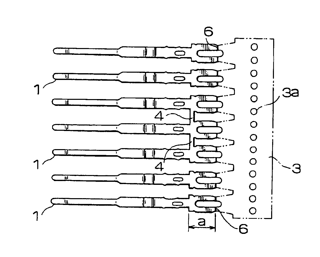
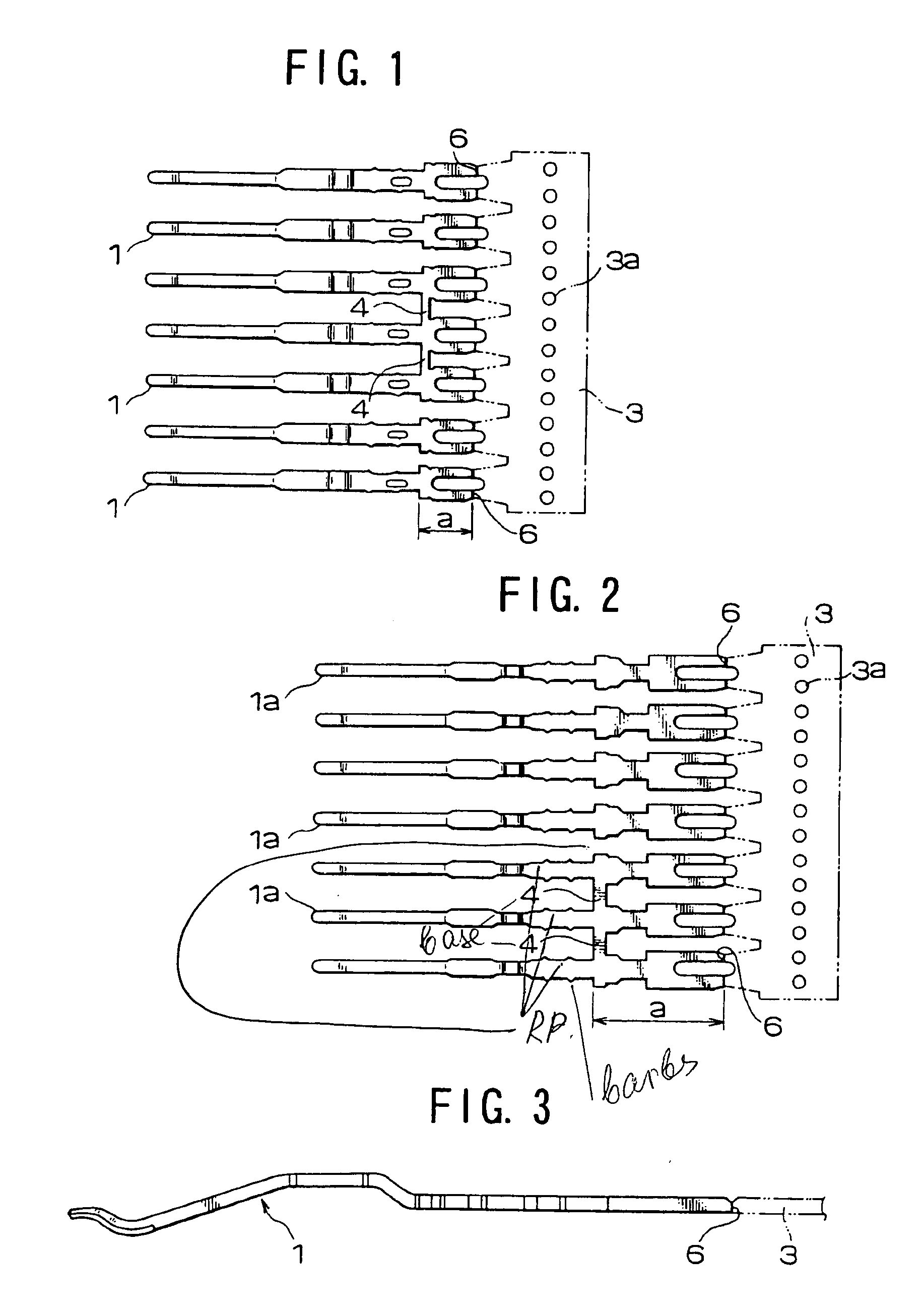
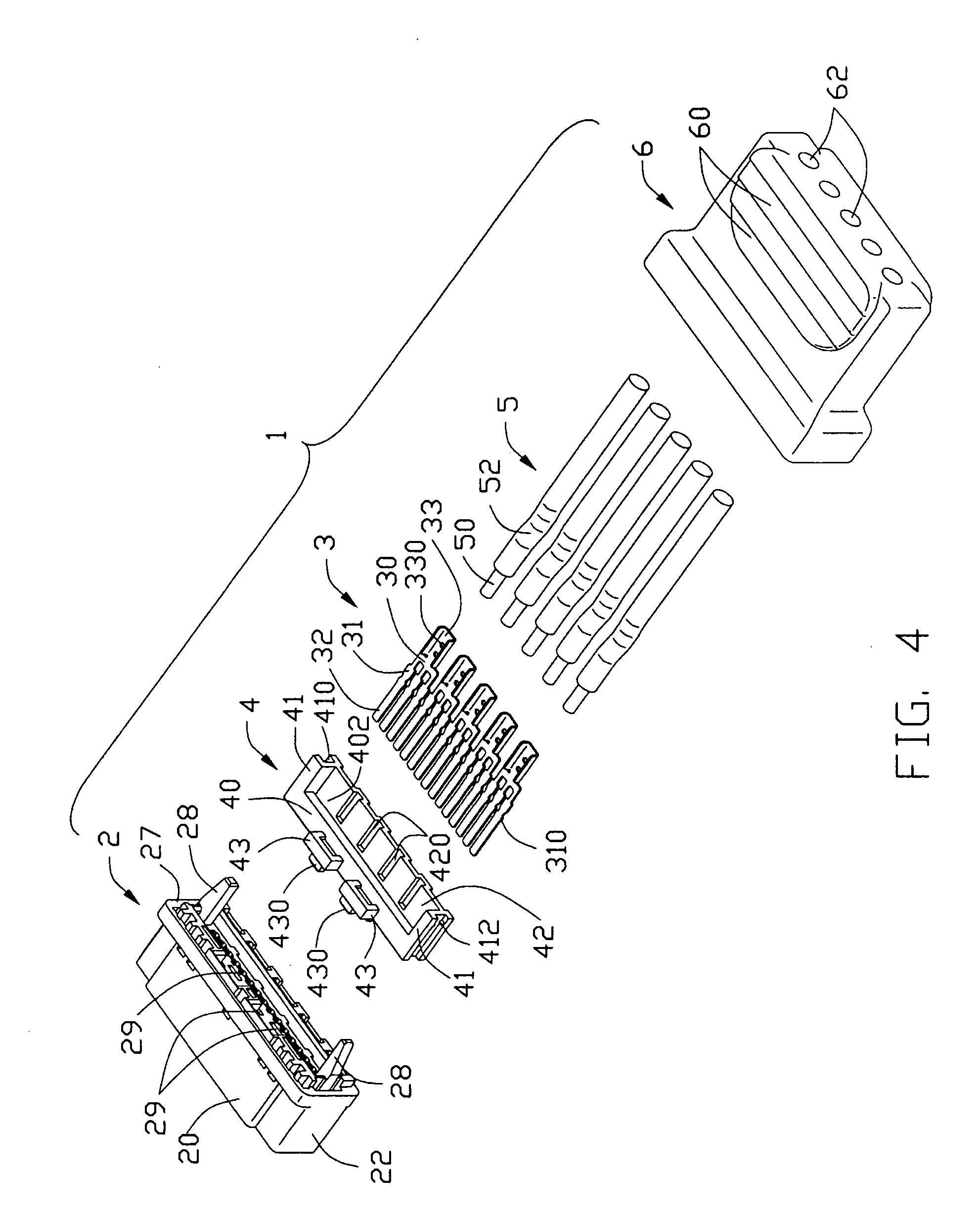
[0021] Referring to FIGS. 1 to 4, a cable end connector assembly 1 in accordance with the present invention comprises an insulative housing 2, a plurality of contact units 3 received in the insulative housing 2, a spacer 4 attached to the insulative housing 2, a plurality of wires 5 electrically connected to corresponding contact units 3, and a cover 6. In the preferred embodiment of the present invention, the cable end connector assembly 1 is a Serial ATA cable end connector assembly.

[0022] The insulative housing 2 comprises a top wall 20, a bottom wall 21 opposite to the top wall 20, a pair of sidewalls 22 connecting the top and bottom walls 20, 21, and a rear wall 27, which together define a receiving space 23. An L-shaped tongue 24 extends forwardly from the rear wall 27 and into the receiving space 23. A plurality of passageways 25 is defined in a bottom face of the L-shaped tongu...


PUM


Abstract

A cable end connector assembly (1) includes a housing (2), a number of contact units (3), a spacer (4), a number of wires (5), and a cover (6). The housing includes a pair of keys (28) in a rear wall thereof. Each contact unit comprises three mating portions (32) and a U-shaped tail portion (33) opposite to the mating portion. The spacer comprises a number of through holes (400) extending therethrough, a supporting portion (42) supporting the U-shaped tail portions, and a pair of keyways (410). The supporting portion defines a number of grooves (420) in a top surface thereof. Each wire comprises a conductive core (60) received in and soldered with the tail portion. The cover is over-molded with a rear end of the housing and front ends of the wires.

Description

BACKGROUND OF THE INVENTION [0001] 1. Field of the Invention [0002] The present invention generally relates to a cable end connector assembly, and more particularly to a Serial Advanced Technology Attachment (Serial ATA) cable end connector assembly with an improved spacer for providing good electric transmission performances. [0003] 2. Description of Related Art [0004] There exists in the art an electrical connector known as a Serial ATA connector, which is generally used for disk drives and storage peripherals connecting with a mother board. Generally, a Serial ATA cable end connector assembly comprises a housing with a plurality of terminals therein and a cable having a plurality of wires. Tail ends of the terminals terminate the wires of the cable. For positioning the terminals, the Serial ATA cable end connector assembly usually further includes a spacer attached to the housing. [0005] U.S. Pat. No. 6,623,299 B1 discloses such a Serial ATA cable end connector assembly having a ...

Claims


Application Information

Patent Timeline
Patent Type & Authority Applications(United States)
IPC IPC(8): H01R12/24H01R13/02H01R13/40H01R13/405H01R13/46H01R13/58H01R13/648H01R24/00
CPCH01R13/405H01R23/661H01R13/5845H01R12/00
Inventor WU, JERRY
Owner HON HAI PRECISION IND CO LTD
Why Eureka
Try Eureka