Eureka AIR delivers breakthrough ideas for toughest innovation challenges, trusted by R&D personnel around the world.

Spinal cage insert, filler piece and method of manufacturing

a technology of spinal cage and filler piece, which is applied in the direction of manufacturing tools, joint implants, prostheses, etc., can solve the problems of insufficient placement of structural or bone-growth-promoting materials immediately between vertebrae, limited use of ceramic as spinal cage filler material, and inability to achieve the effect of promoting bone growth and promoting bone growth

Inactive Publication Date: 2005-08-11
THERICS
View PDF59 Cites 122 Cited by
  • Summary
  • Abstract
  • Description
  • Claims
  • Application Information

AI Technical Summary

Problems solved by technology

To date, the use of ceramic as spinal cage filler material has been limited to loose materials such as granular materials.
As such, the ceramic filler material has not had any designed-in macroscopic geometric features which might help encourage the ingrowth of natural bone.
In spinal fusion procedures, sometimes it is not possible to place enough of either structural or bone-growth-promoting material immediately between vertebrae in the space formerly occupied by the disc.
However, the article described in that patent is only a polymeric resorbable membrane rolled into a cylindrical shape, and so the body of the described device does not contain calcium phosphate which is known to be useful for facilitating bone ingrowth.
The article described in that patent also has only limited control of its structure at various dimensional scales.
Other surgical procedures which have reinforced the external posterior of vertebrae have generally done so with metal rods or instrumentation, which have of course been nonresorbable and incapable of hosting any bone ingrowth.
However, except as described in commonly assigned patent application “Methods and apparatus for engineered regenerative biostructures such as hydroxyapatite substrates for bone healing applications,” U.S. application Ser. No. 10 / 122,129, docket number 900122.432, rigid filler material has typically been featureless block having isotropic structure and geometry, and the material has not offered the bone ingrowth advantages which are possible with surface features such as recesses and / or channels.
A frequent concern has been distortion of dimensions and shape during sintering, especially for large articles, because sintering of an article made initially from powder can involve shrinkage of overall dimensions by as much as 20%.
Such practical difficulties with sintering have made it difficult to sinter articles having relatively large overall dimensions.
However, in general, adding DBM to an article could not be done simply by soaking an already-manufactured article in a liquid, because DBM is generally used in the form of particles greater than a certain minimum size, typically 100 micrometers.
However, this approach has only been applicable to osteoinductive substances which are liquids.
There has been no way to introduce DBM particles into porous structures because, as mentioned, there is a size which DBM particles have to have to be effective and even if such pores existed in structures those pores were inaccessible for introducing particles of DBM into them.
Thus, basically there has been a limitation against the use of solid particulate osteoinductive materials as an additive to implantable structures.
More specifically there has been no way to use DBM, which is an excellent osteoinductive material, in rigid osteoconductive structures.

Method used


Image

  • Spinal cage insert, filler piece and method of manufacturing
  • Spinal cage insert, filler piece and method of manufacturing
  • Spinal cage insert, filler piece and method of manufacturing

Examples


Embodiment Construction

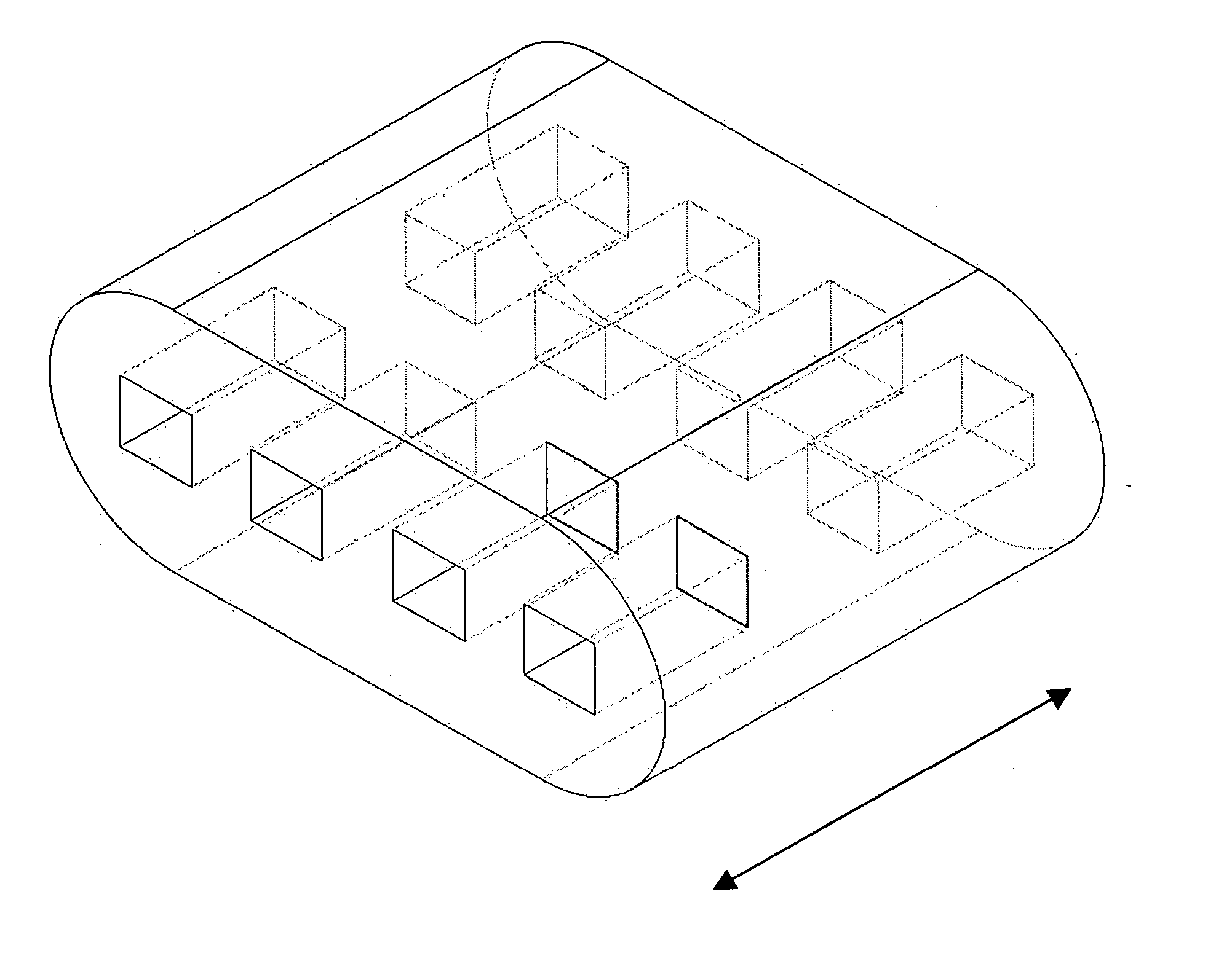
[0056] Some embodiments of the invention may include bone void filler pieces of shapes suitable for implantation in a bone void that was surgically created or that otherwise resulted from other conditions such as disease or traumatic injury.

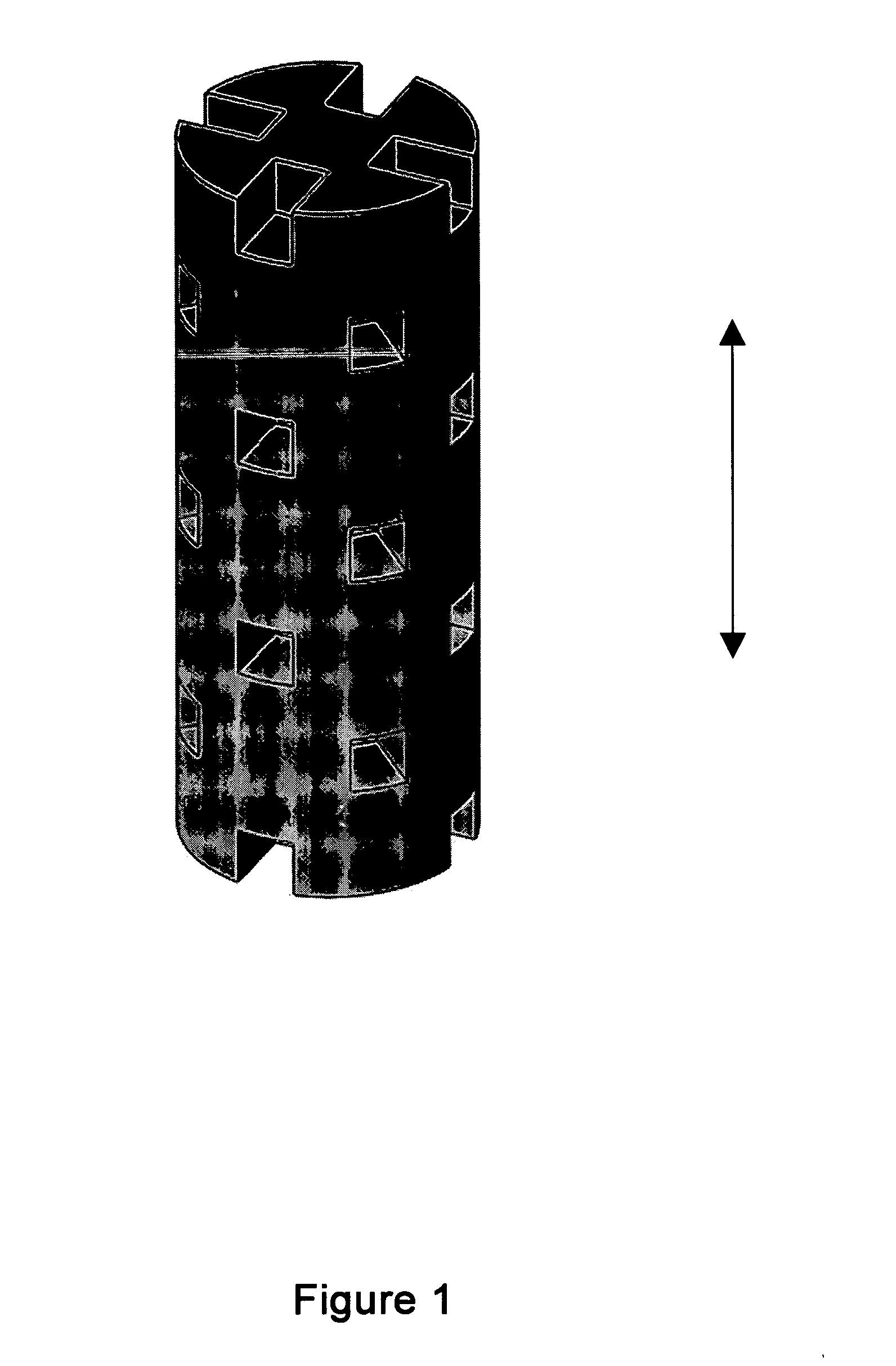
[0057] Some embodiments of the invention provide articles which promote bone growth. These articles may be placed in the interior of a spinal cage (spinal cage inserts).

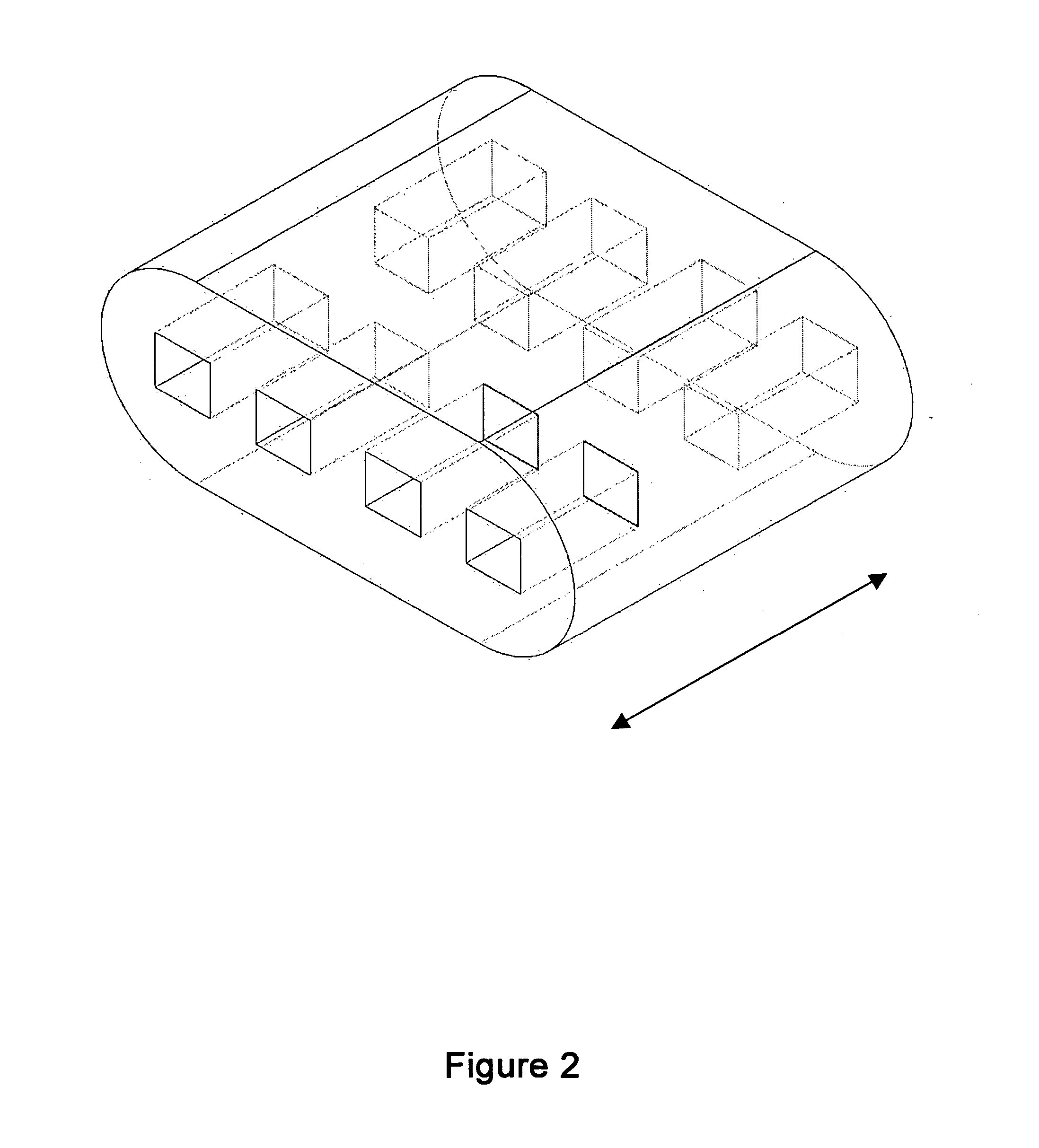
[0058] Some embodiments of the invention provide bone-growth-promoting articles (e.g., filler pieces) which may be placed at exterior surfaces of vertebrae. These various articles can be specified and manufactured in terms of their material composition and also in terms of their geometry. Some embodiments are directed to methods of manufacturing such articles.

[0059] According to some embodiments, the spinal cage insert and / or filler piece (either of which may be referred to as an article) may be made of particles of a matrix material which are partially joined directly to each ...


PUM

PropertyMeasurementUnit
Lengthaaaaaaaaaa
Lengthaaaaaaaaaa
Lengthaaaaaaaaaa

Abstract

A spinal cage insert for a spinal cage is provided. The spinal cage insert has a shape suitable to be inserted into and fit closely in an interior of the spinal cage. The insert may comprise a member of the calcium phosphate family. The spinal cage insert may be made to a desired shape of porous ceramic, and it may include channels and / or surface features. Various shapes of filler pieces are also provided, wherein the filler pieces may be suitable to augment external regions of vertebrae which have been fused to each other so as to promote build-up of bone. The spinal cage insert and / or the filler pieces may be osteoconductive and may also contain osteoinductive substances or material. The articles may also contain cavities suitable for containing particles of demineralized bone matrix (DBM). Methods of use and methods of manufacturing the spinal cage insert and filler pieces are also provided.

Description

CROSS-REFERENCE TO RELATED APPLICATIONS [0001] This application claims the benefit of U.S. Provisional Application No. 60 / 512,514, filed Oct. 17, 2003, U.S. Provisional Application No. 60 / 512,417, filed Oct. 17, 2003, U.S. Provisional Application No. 60 / 569,921,filed May 10, 2004, and U.S. Provisional Application No. 60 / 583,670, filed Jun. 28, 2004, the disclosures of each of which are herein incorporated by reference in their entireties.FIELD OF THE INVENTION [0002] The invention pertains to devices that can be coupled to bones as part of a surgical repair of bone disorders such as spinal disorders. BACKGROUND OF THE INVENTION [0003] Treatment of spinal disorders, such as for remediation of herniated or degenerated discs or other spinal problems, sometimes involves fusion of adjacent vertebrae to each other (arthrodesis). Spinal fusion involves inserting between vertebrae, in place of the normal intervertebral disc, material which may be a combination of structural material and mat...

Claims


Application Information

Patent Timeline
IPC IPC(8): A61FA61F2/00A61F2/02A61F2/28A61F2/30A61F2/44A61F2/46B29C67/04
CPCA61F2/28A61F2310/00293A61F2/4455A61F2002/2835A61F2002/30059A61F2002/30062A61F2002/30153A61F2002/30154A61F2002/30224A61F2002/30225A61F2002/30235A61F2002/30263A61F2002/30271A61F2002/30354A61F2002/30403A61F2002/30599A61F2002/30772A61F2002/30785A61F2002/30807A61F2002/30813A61F2002/30815A61F2002/30822A61F2002/30957A61F2002/30985A61F2210/0004A61F2220/0025A61F2220/0033A61F2230/0019A61F2230/0021A61F2230/0069A61F2230/0082A61F2230/0084A61F2250/0063A61F2/30744A61F2002/30261A61F2002/30593
Inventor SHAPPLEY, BENPRYOR, TIMOTHYBLUM, JOHNBRADBURY, THOMAS J.MATERNA, PETER A.MCGLOHORN, JONATHANWEST, THOMAS GEORGESAINI, SUNILHATCHER, THOMAS JAMESRECBER, ALI CEM
Owner THERICS
Why Eureka
Eureka Blog
Learn More