Method and system for controlling a transfer case clutch to protect against excessive heat

a technology of transfer case and clutch, which is applied in the direction of fluid couplings, couplings, instruments, etc., can solve the problems of affecting the performance of the clutch, the surface wear of the plate and disc, and the clutch to develop heat, so as to achieve precise clutch control, increase the clutch cooling capacity, and reduce the effect of clutch slip

Inactive Publication Date: 2005-08-11
FORD GLOBAL TECH LLC
View PDF12 Cites 50 Cited by
  • Summary
  • Abstract
  • Description
  • Claims
  • Application Information

AI Technical Summary

Benefits of technology

[0011] The control method and system of this invention provides higher clutch cooling capacity and, because of this, permits greater clutch slip. The control also provides precise clutch control capability especially at slower speeds. Th

Problems solved by technology

This partial engagement or clutch slip causes the clutch to develop heat as it attempts continually to synchronize the speed of the clutch output and the input.
Friction wear

Method used


Image

  • Method and system for controlling a transfer case clutch to protect against excessive heat
  • Method and system for controlling a transfer case clutch to protect against excessive heat
  • Method and system for controlling a transfer case clutch to protect against excessive heat

Examples


Embodiment Construction

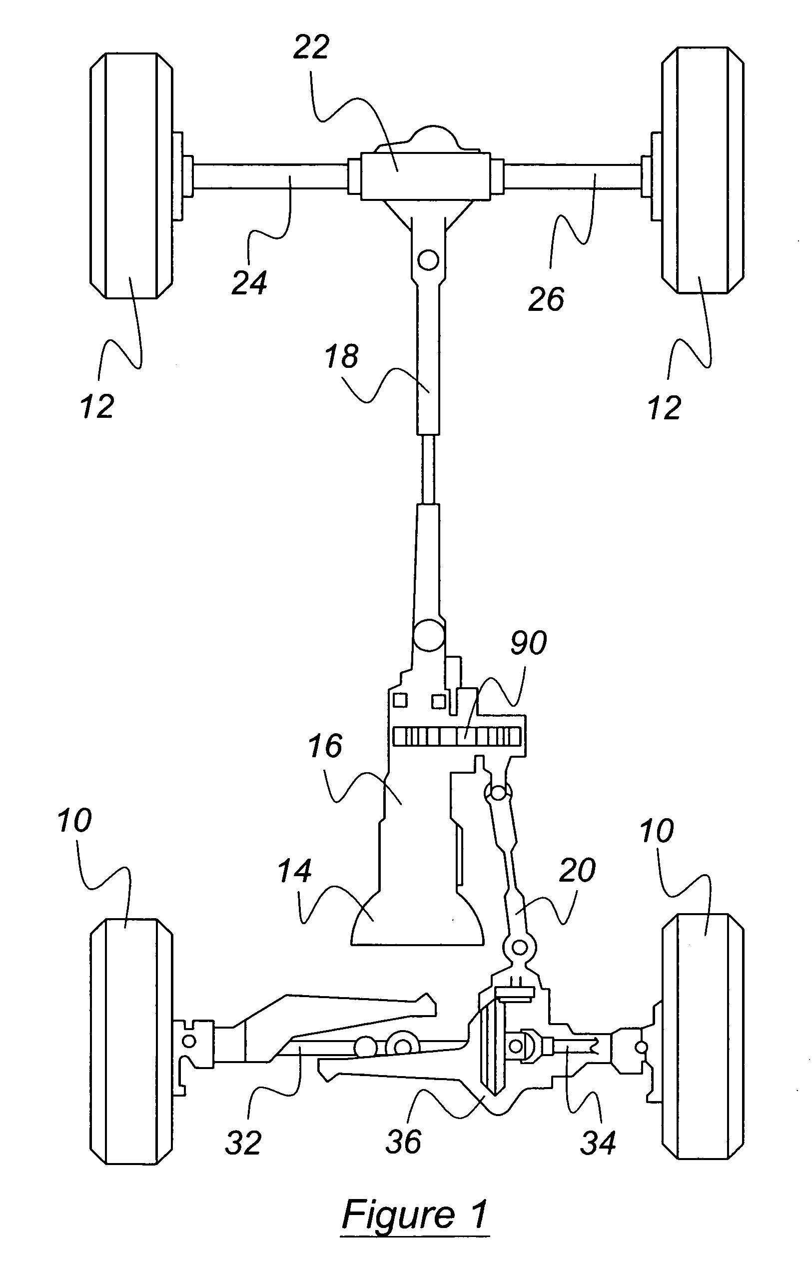
[0020] With reference now to the drawings and particularly to FIG. 1, the powertrain of a motor vehicle, to which the present invention can be applied, includes front and rear wheels 10, 12, a power transmission 14 for producing multiple forward and reverse speed ratios driven by an engine (not shown), and a transfer case 16 for continuously driveably connecting the transmission output to a rear drive shaft 18. The transfer case 16 selectively connects the transmission output to both the front drive shaft 20 and rear drive shaft 18 when a four wheel drive mode of operation is selected, either manually or electronically. Shaft 18 transmits power to a rear wheel differential mechanism 22, from which power is transmitted differentially to the rear wheels 12 through axle shafts 24, 26, which are contained within a differential housing. The front wheels are driveably connected to right-hand and left-hand axle shafts 32, 34, to which power is transmitted from the front drive shaft 20 thro...


PUM


Abstract

In a motor vehicle driveline including a transfer case whose output is continually connected to a first output, a clutch, operating partially engaged, responds to a control signal to change the degree of clutch engagement, whereby a second output is connected driveably to the first output. A digital computer continually calculates a change in clutch temperature at frequent intervals and updates a running sum of clutch temperature changes. The control causes the clutch to more fully engage if the current calculated clutch temperature exceeds a predetermined reference clutch temperature.

Description

BACKGROUND OF INVENTION [0001] 1. Field of the Invention [0002] This invention relates to the field of transfer cases for motor vehicles; more particularly it pertains to control strategies and systems for such transfer cases. [0003] 2. Description of the Prior Art [0004] A transfer case is a device located in a motor vehicle drive line between the output of a geared power transmission and front and rear driveshafts for transmitting power to the wheels. A transfer case may include a planetary gear set that produces both a high range, in which the transfer case output is driven at the same speed as the input, and a low range, in which the output is driven slower than its input speed. The 4×2 and 4×4 states of the transfer case are usually selected manually by the vehicle operator by operating a lever or switch. A first position of the lever causes a range selection device in the transfer case to direct power from the transmission output to a rear drive axle, the 4×2-drive mode. A sec...

Claims


Application Information

Patent Timeline
IPC IPC(8): B60K23/08F16D48/06G06F17/00
CPCB60K23/0808Y10T477/606B60W2510/0291B60W2710/023F16D48/066F16D2500/1026F16D2500/10431F16D2500/30402F16D2500/30405F16D2500/30406F16D2500/30412F16D2500/30421F16D2500/50296F16D2500/70406F16D2500/70424Y10T477/75B60W2510/0275
Inventor JIANG, HONGSANKPAL, BALTHOMAS, STEVENALLEN, TIMOTHY
Owner FORD GLOBAL TECH LLC
Why Eureka
Try Eureka