
Method of waterproof of electric cable joint

a technology of waterproofing and electric cables, applied in the direction of dustproof/splashproof/drip-proof/waterproof/flameproof connection, cable termination, cable connection, etc., can solve the problems of air bubbles, reduced waterproof and electric insulation of electric cables, and longer curing time, so as to prevent leakage of sealing materials from the lower side opening, the effect of improving the appearance and quality of the electric cable join

Inactive Publication Date: 2005-08-18
YAZAKI CORP
View PDF8 Cites 15 Cited by
  • Summary
  • Abstract
  • Description
  • Claims
  • Application Information

AI Technical Summary

Benefits of technology

[0017] An object of the present invention is to provide a method of waterproof of an electric cable joint wherein air bubbles are removed quickly, the waterproof and electric insulation of the electric cable joint is stably increased, and the productivity of the electric cable joint is increased.

Problems solved by technology

However, at the conventional method of waterproof of an electric cable joint, when a sealing material is injected into a cap, air bubbles remain in the sealing material, especially in urethane foam.
When the sealing material solidifies with the air bubbles remained, cracks or holes connecting the air bubbles easily occur and water penetrates into the sealing material through the cracks and holes resulting to the reduction of the waterproof and electric insulation of the electric cable joint.
If the viscosity of the sealing material is lowered to remove air bubbles quickly, the flow becomes high so that, when the joint is inserted into the cap, the sealing material spills over the cap opening and soils the cap, the curing time becomes longer and reduces the productivity.

Method used


Image

  • Method of waterproof of electric cable joint
  • Method of waterproof of electric cable joint
  • Method of waterproof of electric cable joint

Examples


Embodiment Construction

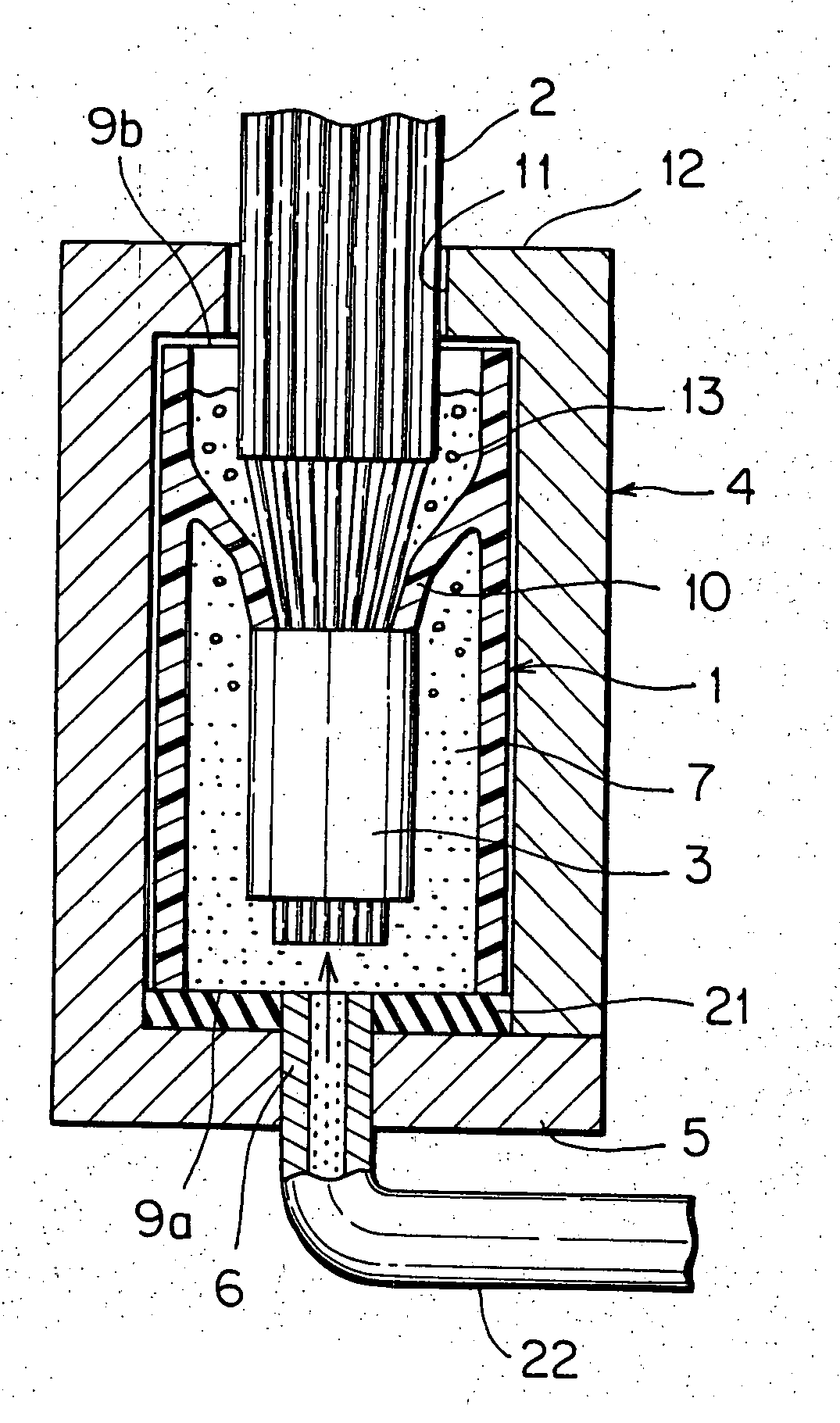
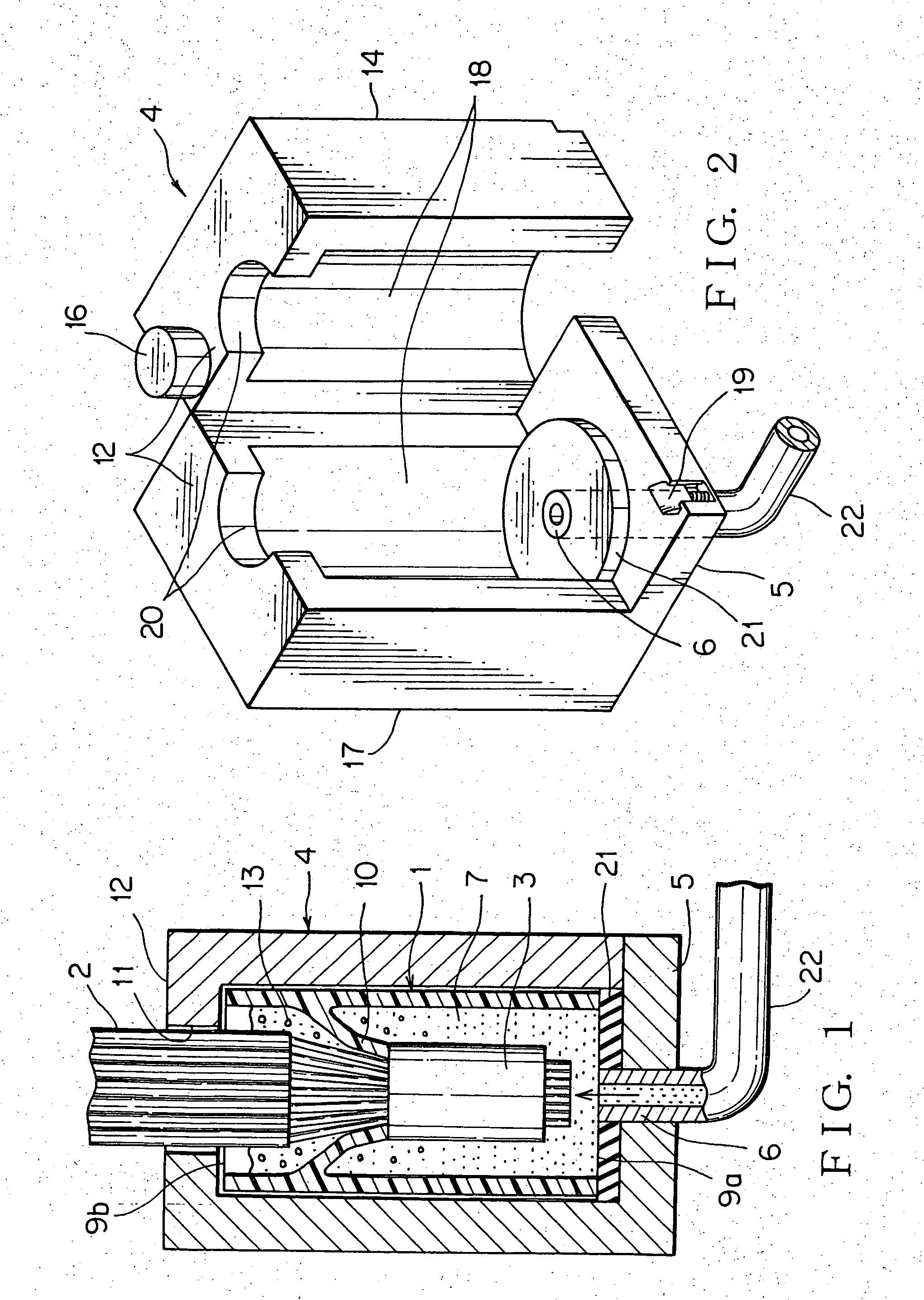
[0039]FIGS. 1 and 2 show an embodiment of a method of waterproof of an electric cable joint according to the present invention.

[0040] The method of waterproof of the electric cable joint utilizes a generally cylindrical cap 1 made of synthetic resin having a vertical through-hole (a top and bottom opening 9a and 9b). The joint 3 of the electric cable 2 is inserted into the cap, keeping the electric cable 2 upward and the joint 3 downward, and the cap 1 is set inside a holder 4 and a sealing material 7 is injected by a injection nozzle 6, which penetrates a bottom wall 5 of the holder 4, into the cap upward from the lower side.

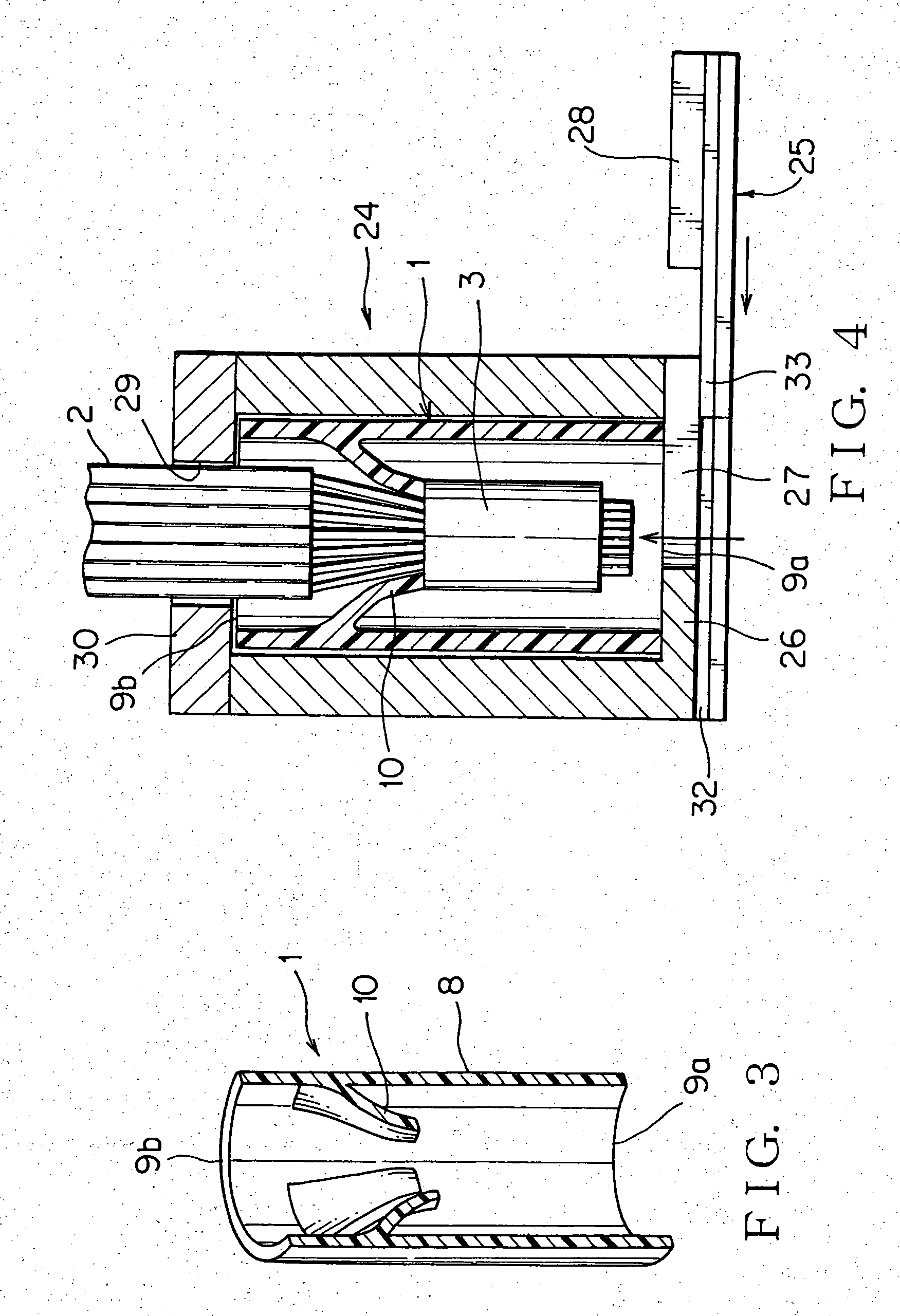
[0041] The cap 1 is provided with a cylindrical cap main body 8 and a flexible locking lance 10 which projects into a front (lower) opening 9a from the inner face of the cap main body 8 as shown in FIG. 3 (a vertical sectional view). The front opening means the opening locating to the front end side of the joint when the joint 3 is fitted.

[0042] The cap main...


PUM

PropertyMeasurementUnit
waterproofaaaaaaaaaa
timeaaaaaaaaaa
electric potentialaaaaaaaaaa

Abstract

The object of the present invention is to inject a sealing material into a cap receiving an electric cable joint without remaining air bubbles. The cap having an opening at both ends receives an electric cable joint, the electric cable being in the upper side and the joint being in the lower side, the sealing material is injected into the cap from the lower opening. Moreover, the sealing material is injected into the cap having the opening at the top and bottom from the lower opening and the electric cable joint is inserted into the cap from the upper opening. Moreover, the electric cable joint is received in the cap having the opening at both sides, the sealing material is injected into the cap from the upper opening and the cap is reversed up and down to leave. Moreover, the sealing material is injected into the cap having the opening at both sides, from the upper opening and the electric cable joint is inserted into the cap and the cap is reversed up and down to leave. It is utilized that the cap holder receives the cap in the state that the upper and / or lower opening of the cap is covered.

Description

BACKGROUND OF THE INVENTION [0001] 1. Field of the Invention [0002] The present invention relates to a method of waterproof of an electric cable joint intended for waterproof and insulation of the joint, wherein the electric cable joint is received in a cap and a seal material is injected in the cap. [0003] 2. Related Art [0004]FIGS. 7 and 8 show a conventional method of waterproof of electric cable joint described in the published patent application H10-243539 (pp.3-4 and FIGS. 1-5) (JP,10243539,A) referred to as Patent Document 1. [0005] The method of waterproof of an electric cable joint constitutes the steps of injecting a sealing material 52 from above into a cap 51 made of synthetic resin standing, inserting a joint 54 of an electric cable 53 from above, fixing the electric cable 53 to an extension 55 of the cap 51 by a tape 56, and solidifying the sealing material 52 in an ambient atmosphere. [0006] The joint 54 is formed by stripping an insulation cover of each end of a plur...

Claims


Application Information

Patent Timeline
Patent Type & Authority Applications(United States)
IPC IPC(8): H01R4/70H01R13/52H01R43/00H02G15/04
CPCH01R13/5216H01R43/005H02G15/043Y10T29/49117Y10T29/49194Y10T29/49176Y10T29/49172Y10T29/49171Y10T29/49174
Inventor TORII, CHIEKOYAMAMOTO, TAKAYUKIOZAWA, MASATO
Owner YAZAKI CORP
Learn More