
Loading dock seal with flow through vent

a vent and dock seal technology, applied in the direction of roofs, loading/unloading, construction, etc., can solve the problems of high temperature in the loading area, heat can be very uncomfortable for workers loading and unloading goods, and the effect of increasing the visibility of the dock seal system

Inactive Publication Date: 2005-08-18
SHELTON MICHAEL J
View PDF37 Cites 10 Cited by
  • Summary
  • Abstract
  • Description
  • Claims
  • Application Information

AI Technical Summary

Benefits of technology

[0017] An advantage of the present invention, is that by having passageways through the dock seal system, covered by at least a substantially transparent material, increased visualization through the dock seal system may occur, reducing blind areas, and increasing area safety and light.
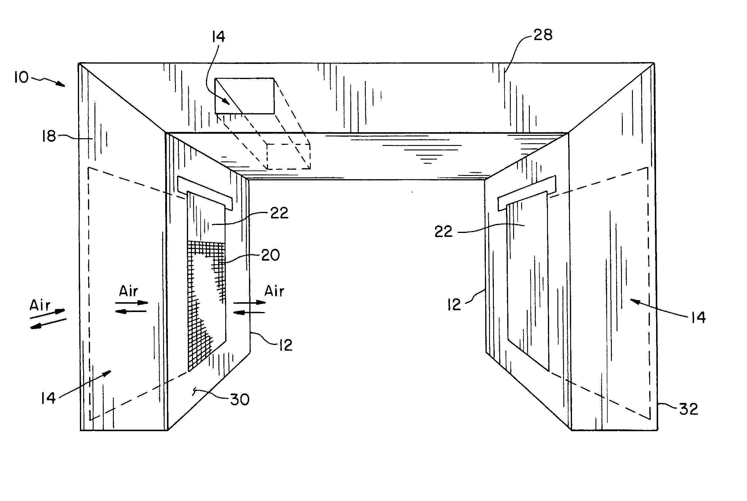
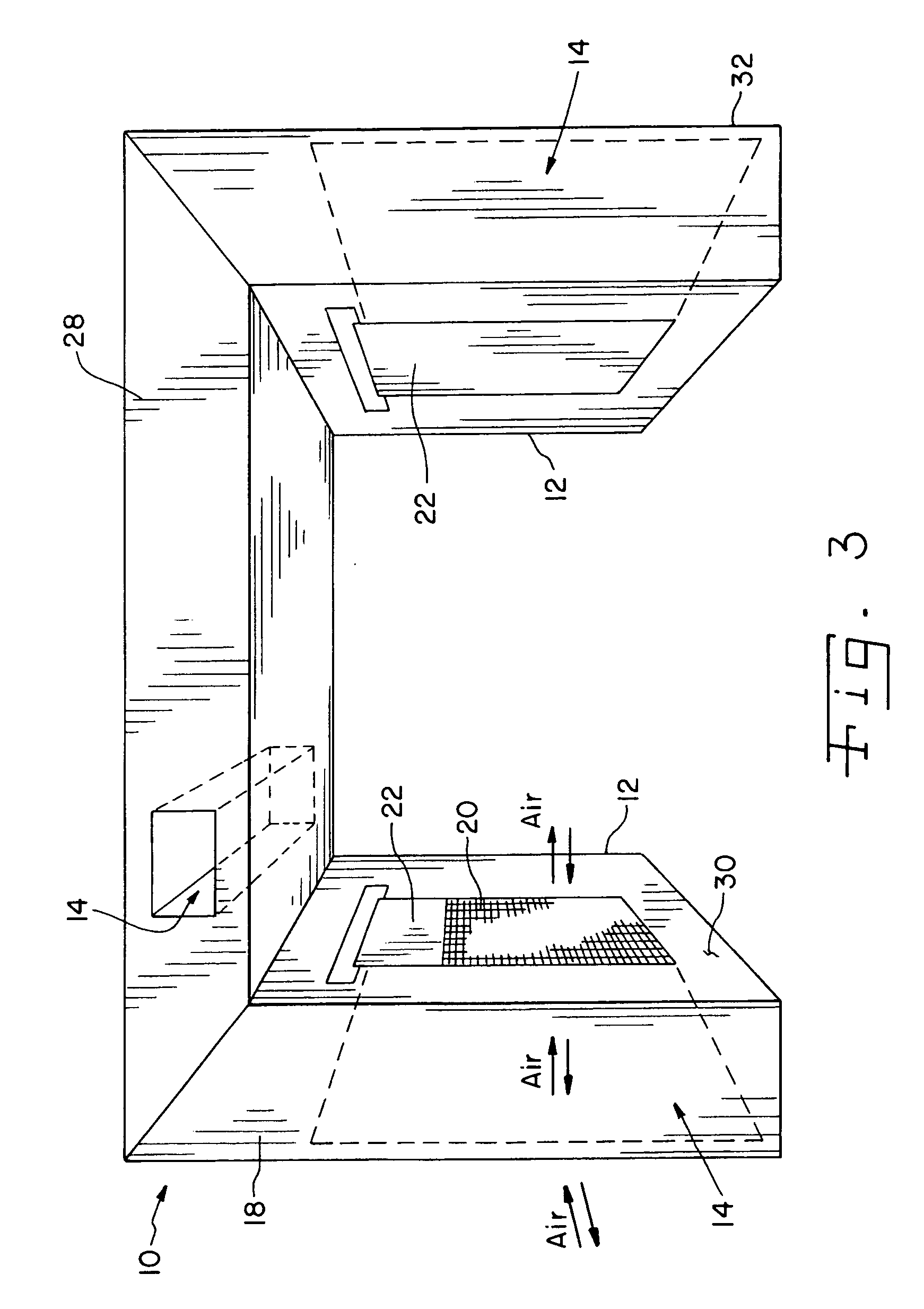
[0018] An advantage of the present invention is that, by forming passageways into the loading dock seal and by at least one of the passages having a mesh segment adjacent to or through the passage, the mesh segment is able to allow air to flow and light to pass through the passage and therethrough the loading dock seal to make the loading area a more comfortable environment. The mesh segment also prevents / eliminates rodents, insects, rain, snow and debris from passing through the passage and to the loading dock area.
[0019] Another advantage of the present invention is that, by using a mesh segment cover to cover at least a portion of a mesh segment, air flow through the passages in the loading dock seal can be controlled. Also, the mesh segment cover can completely cover or seal a mesh segment to keep cold weather elements (e.g., cold air, snow) from entering the loading area through the passage while also being either transparent or opaque to light or vision.
[0020] Yet another advantage of the present invention is that rails, rollers or hinges are not used or needed in the construction of the loading dock seal and, therefore, reduced maintenance and construction costs are possible.
[0021] Still another advantage of the present invention is that, by coating the loading dock seal with a material, preferably a UV light shielding vinyl to protect the loading dock seal from solar ultraviolet rays, ultraviolet damage to the loading dock seal can be minimized, while still allowing non UV light to pass through the dock seal system.

Problems solved by technology

This heat insulating effect of loading dock seals can prove problematic in that the temperature can become very hot within the loading area because the hot air cannot escape from the loading dock, and cool air cannot flow thereinto during the loading and unloading process.
This heat can be very uncomfortable for the workers loading and unloading the goods.
Another problem occurs if an opening or gap is intentionally left between the rear of the parked vehicle and the loading dock to allow cool air to enter into the loading area.
Another problem with loading dock seals is that rails, rollers or hinges are typically used in their construction.
If the vehicle backs into the loading dock seal unevenly, at too high of a speed, or without braking, the rails, rollers and hinges can become damaged and require replacement.
This increases the maintenance costs for the loading dock seal.
Furthermore, some materials that could be utilized, for example foam rubber, to construct the loading dock seal may be very quickly damaged and destroyed by the ultraviolet rays from the sun.
Other problems, with prior art dock seals are that, at times visibility from outside the seal to inside, and vise versa, are reduced.

Method used


Image

  • Loading dock seal with flow through vent
  • Loading dock seal with flow through vent
  • Loading dock seal with flow through vent

Examples


Embodiment Construction

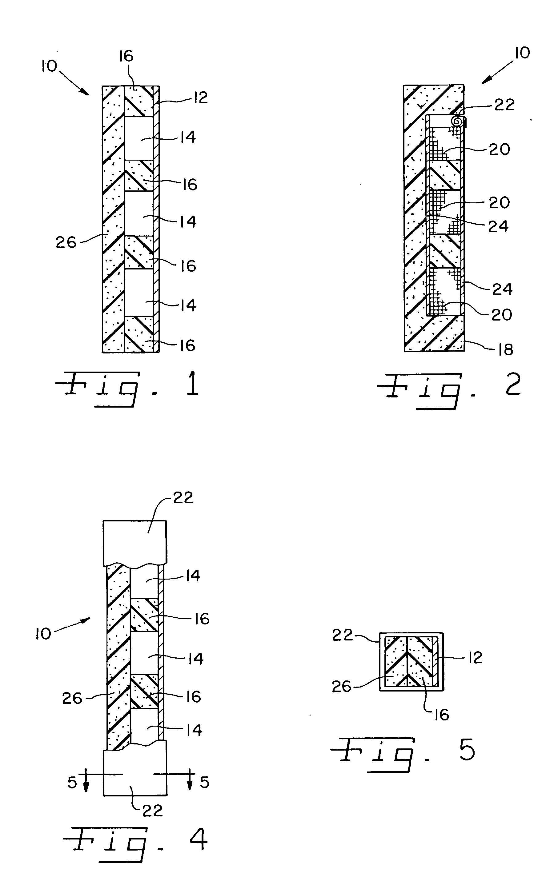
[0029] Referring now to the drawings and particularly to FIG. 1, there is shown one side of the loading dock seal system 10 of the present invention. Loading dock seal 10 has a base 12. Base 12 is constructed from wood, but other materials such as plastic or metal can be utilized therefor. Base 12 is approximately 2″×12″×8′ but other sizes thereof can be utilized as well. Base 12 is connected to a loading dock (not shown) utilizing bolts, fasteners, screws or any other type of connecting device (not shown).

[0030] One or more support members 16 are connected to base 12. Support members 16 are compressible pads made of a foam, rubber, or other elastomeric / resilient material. Support members 16 are connected to base 12 in preferably an evenly spaced apart relationship utilizing glue, bolts, screws, fasteners or other connecting devices. The present invention is not limited to support members 16 being spaced evenly apart but can be spaced at variable distances as well. Also, a single s...


PUM


Abstract

A loading dock seal has one or more recesses formed within the loading dock seal and covered by a transparent material. Mesh segments are utilized to screen some of the recesses to reduce rain, snow, rodents, insects and debris from passing through the recess passageway to the loading dock. A further transparent or opaque mesh segment cover can be utilized to selectively cover one or more of the mesh segments.

Description

CONTINUATION DATA [0001] This application hereby claims the benefit to U.S. application Ser. No. 10 / 445,102, filed May 22, 2003 and is hereby incorporated by reference.BACKGROUND OF THE INVENTION [0002] 1. Field of the Invention [0003] The present invention relates to a loading docking seal having passageways formed therethrough to selectively allow air to flow through the passageways along with movable see through panels to increase visibility therethrough. [0004] 2. Description of the Related Art [0005] A loading dock seal is attached around a loading dock doorway. A vehicle backs up until the rear of the vehicle is in contact with the loading dock seal. Once the rear of the vehicle is in contact or adjacent with the loading dock seal, workers transfer goods between the vehicle and the loading dock. The loading dock seal is utilized to protect the workers from the rain, snow, wind and cold during the loading and unloading process. [0006] The loading dock seal can keep heat from es...

Claims


Application Information

Patent Timeline
IPC IPC(8): B65G69/00
CPCB65G69/008
Inventor SHELTON, MICHAEL J.
Owner SHELTON MICHAEL J
Learn More