Saw blade and saw having an oscillatory drive

Inactive Publication Date: 2005-08-18
C & E FEIN
View PDF9 Cites 36 Cited by
  • Summary
  • Abstract
  • Description
  • Claims
  • Application Information

AI Technical Summary

Benefits of technology

[0008] It is a first object of the invention to disclose a saw with a rotary oscillatory drive that allows for a b

Problems solved by technology

This is a disadvantage, since the exc

Method used


Image

  • Saw blade and saw having an oscillatory drive
  • Saw blade and saw having an oscillatory drive
  • Saw blade and saw having an oscillatory drive

Examples


Embodiment Construction

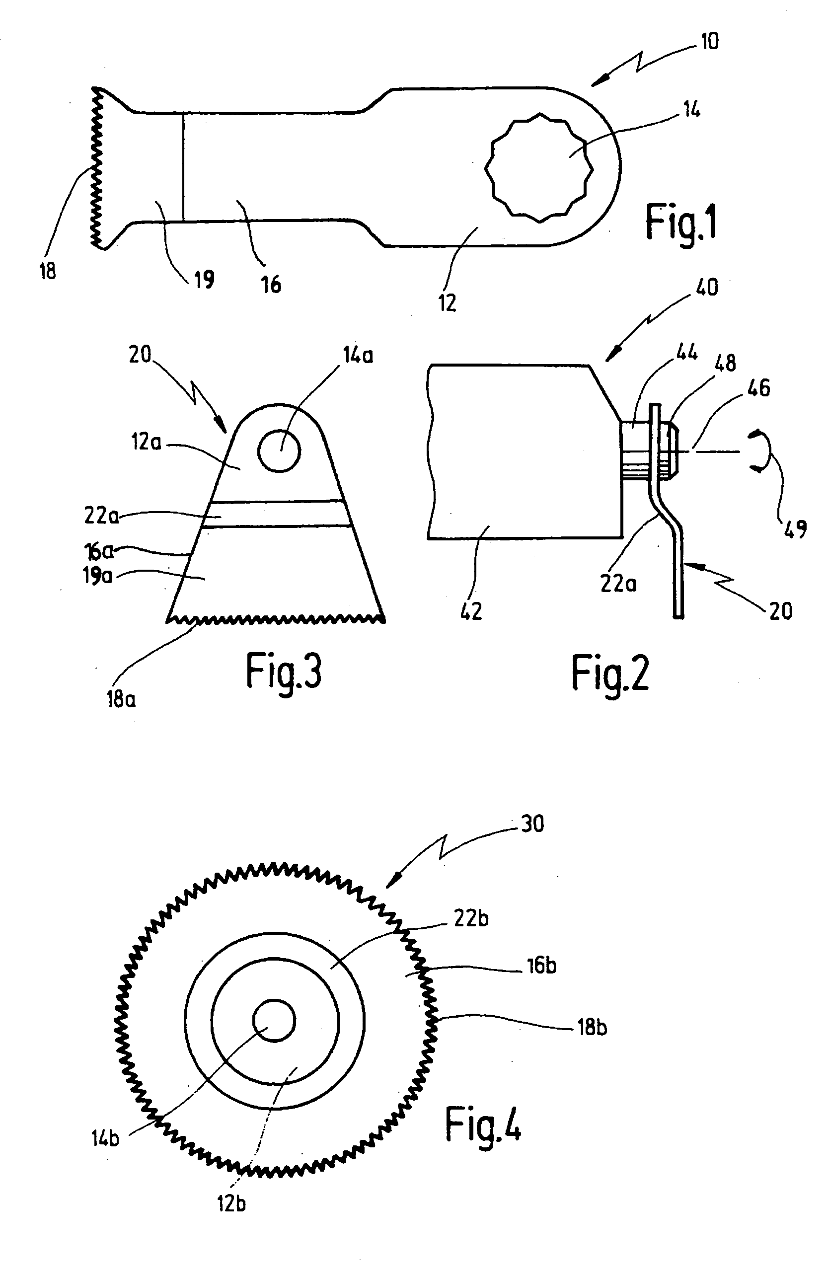
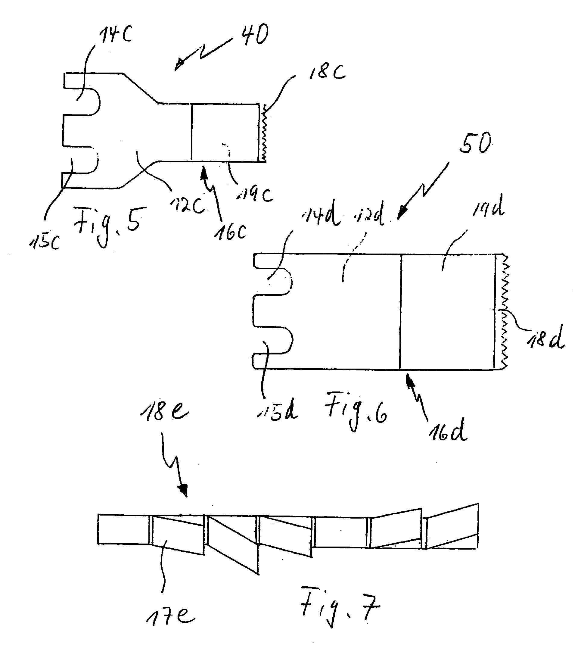
[0043] In FIGS. 1 and 3 saw blades are shown, the basic shape of which is generally known from EP-A-0 881 023. FIG. 4 shows a circular, bent-off saw blade which is also basically known in the prior art. According to the invention, the saw blades according to FIGS. 1 and 3 comprise additional coatings 19 and 19a, respectively, comprising diamond or a hard metal grinding particle.

[0044] All the saw blades described herein are particularly suited for mounting on a free end of a drive shaft of an oscillatory drive.

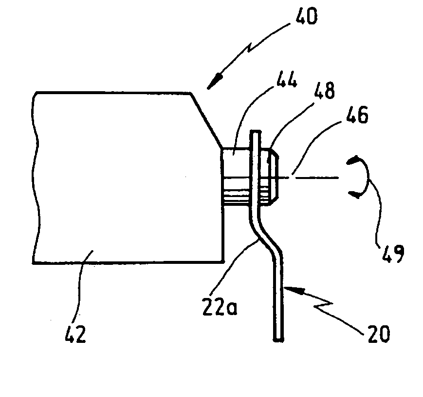
[0045]FIG. 2 shows such a saw 40 comprising an oscillatory drive 42. The oscillatory drive drives a drive shaft 44 about the longitudinal axis 46 of the drive shaft back and forth at high frequency, e.g. between 5,000 and 25,000 oscillations per minute and at a small pivot angle, e.g. 0.5° to 7°, as indicated by the double arrow 49. At the free end of the drive shaft 44 a support for the saw blade is provided which may be placed thereon and which may be fixed by means of a s...


PUM

PropertyMeasurementUnit
Waveaaaaaaaaaa

Abstract

A saw comprising an oscillatory drive for oscillatingly driving a drive shaft about its longitudinal axis is disclosed. The saw comprises a saw blade being driven oscillatingly by the drive shaft and further comprises a mounting section comprising a mounting opening for engaging the drive shaft of the oscillatory drive positively or non-positively. The working section has a cutting edge comprising a series of cutting teeth, wherein at least the cutting edge is made of bimetal. Also preferably there is provided on both sides of the saw blade adjoining the cutting edge a coating comprising diamond grinding particles.

Description

[0001] This application claims priority of pending German Patent Application No. 203 08 797.6 filed May 28, 2003. BACKGROUND OF THE INVENTION [0002] The invention relates to a saw having a rotary oscillating drive motion, comprising a saw blade comprising a mounting section having a mounting opening for engaging a drive shaft which is driven oscillatingly about its longitudinal axis, and further comprising a working section which is provided with a cutting edge having a series of cutting teeth. [0003] Such a saw blade and such a saw are known from EP-A-0 881 023. [0004] Such saw blades are driven by a rotary oscillating drive the drive shaft of which is driven oscillatingly about its longitudinal axis at high frequency in the range between about 5,000 to 25,000 oscillations per minute and at small pivot angle between about 0.5° and 7°. [0005] Using such saw blades in combination with an oscillatory drive special sawing tasks can be performed, such as sawing operations on car body pa...

Claims


Application Information

Patent Timeline
IPC IPC(8): B27B19/00
CPCB27B19/006Y10T83/9379
Inventor THOMASCHEWSKI, WALTER
Owner C & E FEIN
Why Eureka
Try Eureka