
Method and apparatus for applying and distributing particulate material on a substrate

a technology of particulate material and substrate, applied in the field of method and apparatus for applying and distributing particulate material on a substrate, can solve the problems of chopping material, deteriorating material, and not completely satisfying the effect of operation, and achieves the effect of optimum distribution efficiency, simple and reliable, and precise and accurate manner

Inactive Publication Date: 2005-08-18
CARBINPLANT INT AS
View PDF5 Cites 17 Cited by
  • Summary
  • Abstract
  • Description
  • Claims
  • Application Information

AI Technical Summary

Benefits of technology

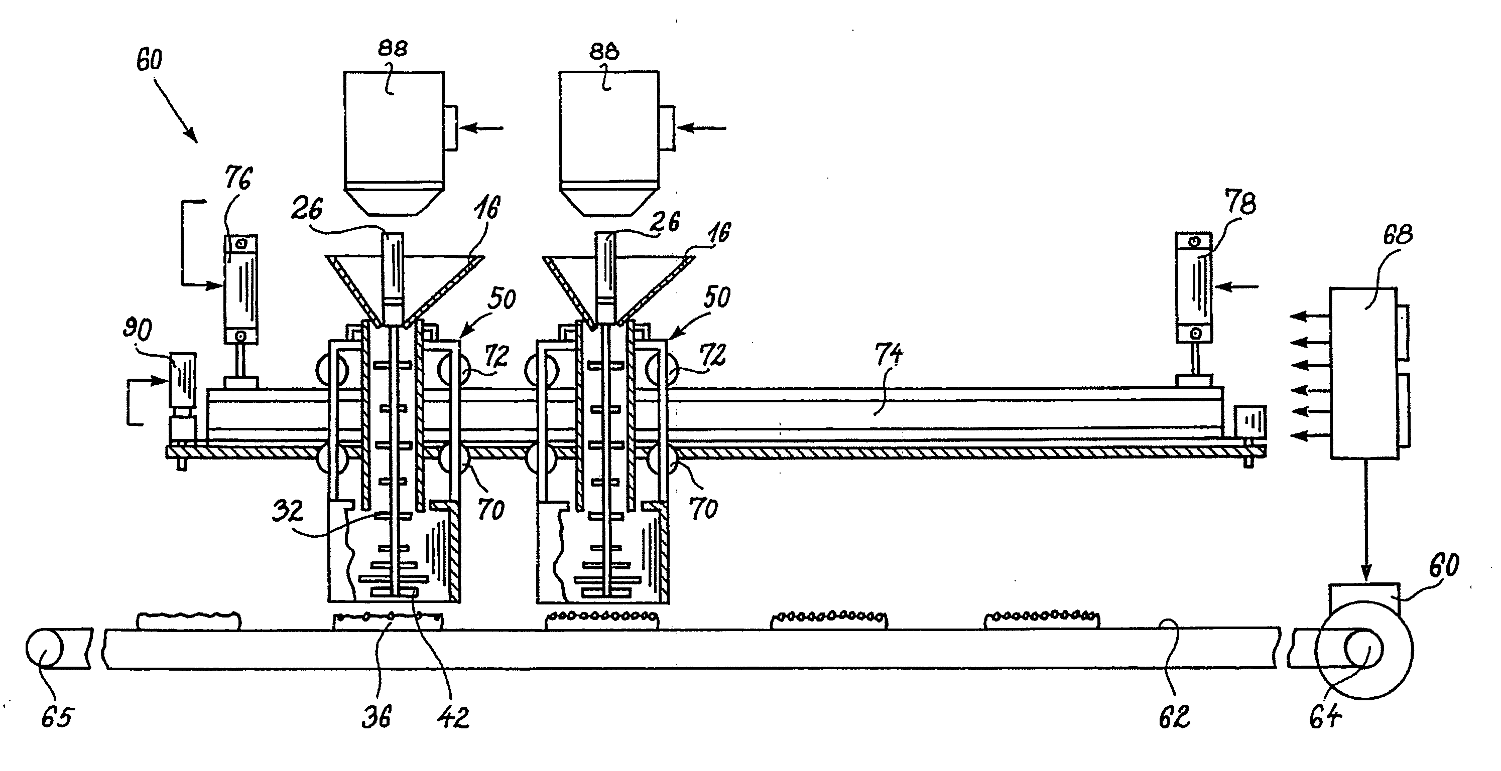
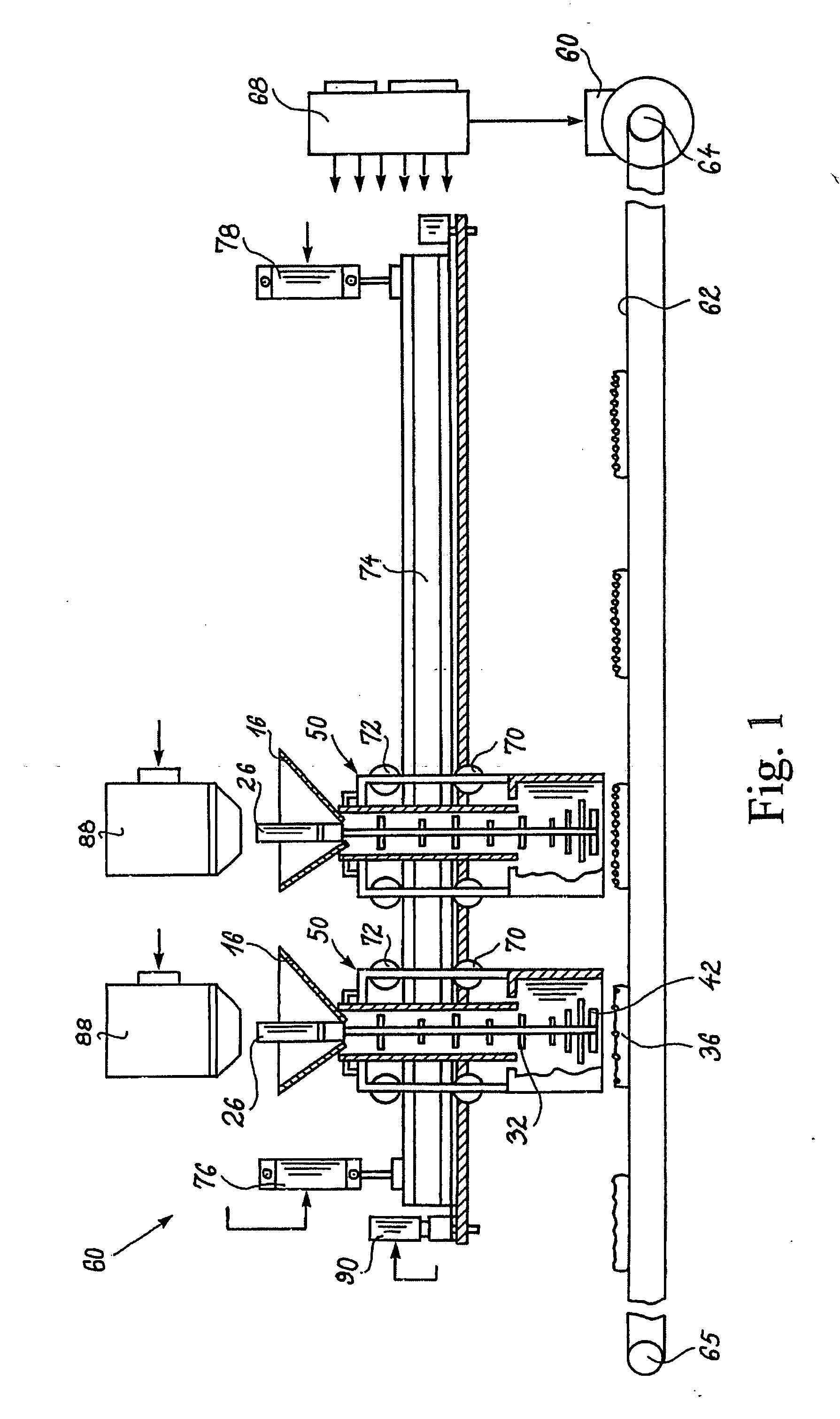
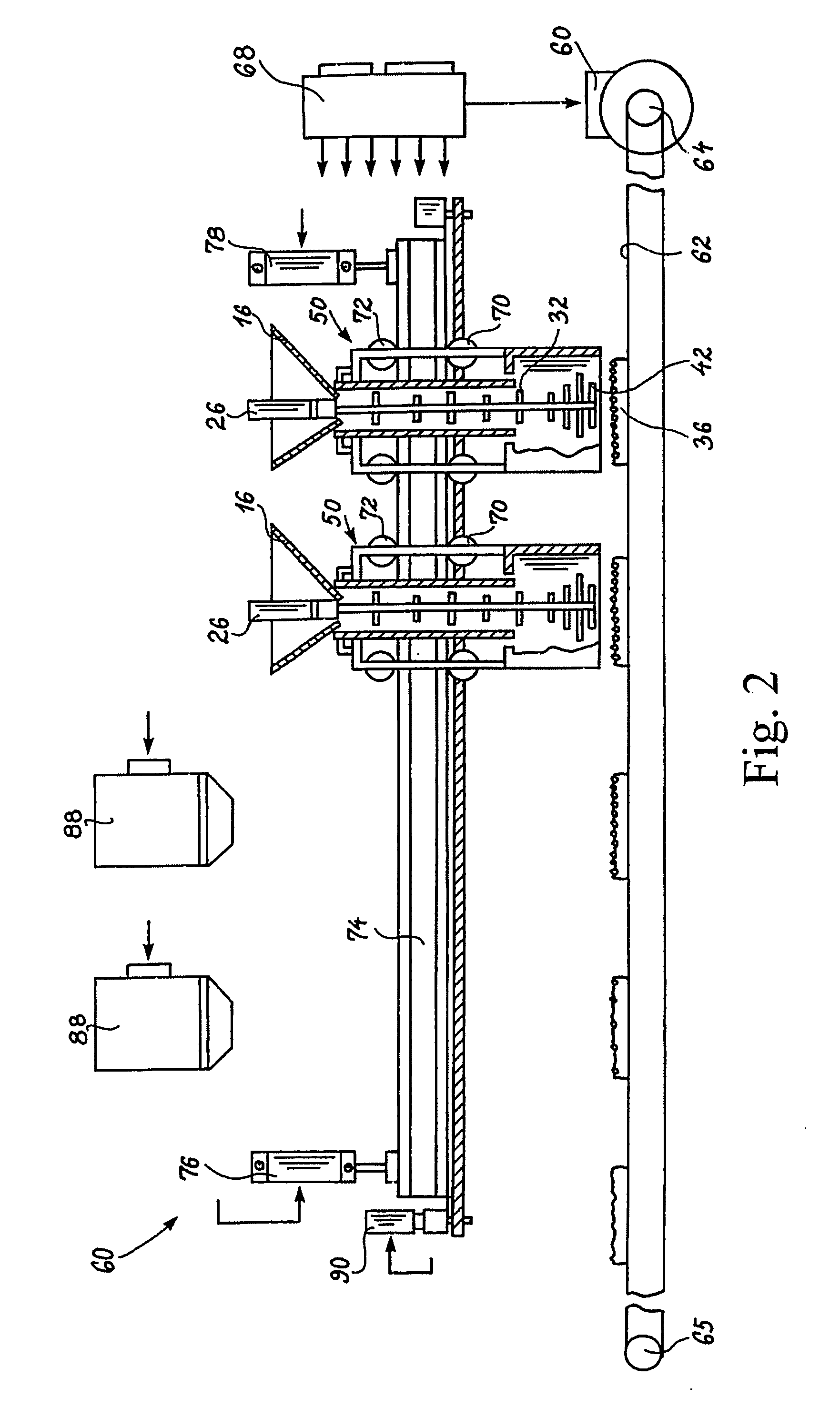
[0010] It is a further advantage of the present invention that the technique of applying and evenly distributing a particulate material onto a substrate such as a pizza or lasagne batter, apart from imposing a minimum impact to the particulate material, causes a minimum wear to the components of the apparatus and at the same time allows the apparatus to be implemented as a simple and reliable apparatus.
[0011] The above object and the above advantage together with numerous other objects, features and advantages will be evident from the following detailed description of the presently preferred embodiment of the technique according to the present invention and in accordance with the teachings of the present invention obtained by a method of applying and distributing a charge of particulate material onto a top surface of a substrate, such as a pizza or lasagne batter, comprising:
[0013] providing a two part separator, a first part of which constitutes a delay line having a first input and a first output, for receiving the charge through the first input, for delaying the transfer of the charge through the delay line and for discharging the charge from the first output, and a second part of which constitutes a diffuser having a second input and a second output, for receiving the charge from the first output of the delay line through the second input and for delivering the charge after spreading the charge through the second output,
[0014] moving the substrate and the two part separator relative to one another for positioning the substrate below the two part separator in a position in registration with the second output,
[0016] moving the substrate and the two part separator relative to one another after the distribution of the charge onto the substrate for removing the substrate from the position below the second output of the two part separator.

Problems solved by technology

Although the prior art distributor apparatuses claim to allow the particulate material, in particular the particulate cheese, to be broken up and distributed evenly, experiments which the applicant company has performed reveal that the charge, when delivered to the distributor, tends to block the even distribution of the material, and therefore the prior art distributors based on rotatable paddles or similar radial blades or paddles have turned out not to function entirely satisfactorily.
The use of rotating paddles or blades for distributing particulate material, e.g. cheese, on a pizza batter, may, apart from the problems of obtaining even distribution of the material, which even distribution may be influenced by the blocking of the material when introduced into the distribution apparatus, further involve certain problems, as the mechanical impact to the material when distributed or spread by means of the rotating paddles or blades may deteriorate the particulate material and generate a chopping of the material rather than a distribution of the material.
Consequently, provided that the prior art rotating paddle or blade distributors are to be improved for providing an even distribution, a risk exists of deteriorating the material by simple chopping the material due to excessive mechanical impact to the particulate material.

Method used


Image

  • Method and apparatus for applying and distributing particulate material on a substrate
  • Method and apparatus for applying and distributing particulate material on a substrate
  • Method and apparatus for applying and distributing particulate material on a substrate

Examples


Embodiment Construction

[0043] In the below description, a technique of applying ingredients is described, such as specific foodstuff constituents e.g. olives, chopped peppers, chopped tomatoes, chopped onion, chopped artichokes, chopped mushrooms, chopped ham, chopped beef, chopped pork, chopped mutton, chopped chicken, chopped turkey in fresh, boiled, roast or smoked form, chopped or cut-up fish, including fresh, roast, boiled or smoked fish parts of, for example mackerel, tuna, herring, flaffish, codfish, salmon, sea trout, etc., and combinations of such foodstuff ingredients, onto a piece of dough, in particular a batter or a paste, more particular onto a pizza batter, before the baking of the batter or dough piece, or alternatively onto a piece of bread or similar substrate. In particular, the below description refers to the application of constituents, being foodstuffs constituents, onto a pizza batter. Still, it is contemplated that the technique and the apparatus and methods implementing the presen...


PUM


Abstract

A method of distributing a charge of particulate material onto a substrate employs a separator having a first part including a first input, a first output, and a delay line for delaying the transfer of the charge from the first input to the first output; and a second part including a diffuser with a second input that receives the charge from the first output, and a second output through which the charge is spread and delivered to the substrate. The substrate and the separator are moved relative to one another for positioning the substrate below the separator in registration with the second output, and the charge is delivered to the first input. After the charge is distributed onto the substrate, the substrate and the separator are again moved relative to one another to remove the substrate from the position in registration with the second output.

Description

CROSS-REFERENCE TO RELATED APPLICATION [0001] This application claims the benefit, under 35 U.S.C. Section 119(e), of co-pending provisional application No. 60 / 553,888, filed Mar. 17, 2004, the disclosure of which is incorporated herein by reference.FEDERALLY SPONSORED RESEARCH OR DEVELOPMENT [0002] Not Applicable BACKGROUND OF THE INVENTION [0003] The present invention relates to a method of applying and distributing a charge of a particulate material onto a top surface of a substrate, such as a pizza or lasagne batter or one or more open sandwiches. The present invention further relates to an apparatus for the application and distribution of the charge of the particulate material onto the top surface of the substrate, such as a pizza or lasagne batter. [0004] Within the technique, several technical solutions for the application and distribution of a charge, such as a charge of a specific foodstuff constituent or a mixture of different foodstuff constituents are known, in particula...

Claims


Application Information

Patent Timeline
IPC IPC(8): A21C9/04A21C15/00G03G13/00
CPCA21C15/002A21C9/04
Inventor SIMONSEN, CARSTEN D.
Owner CARBINPLANT INT AS
Learn More