Throttle apparatus for an internal combustion engine

Inactive Publication Date: 2005-08-18
HITACHI LTD +1
View PDF6 Cites 11 Cited by
  • Summary
  • Abstract
  • Description
  • Claims
  • Application Information

AI Technical Summary

Benefits of technology

[0014] An object of the present invention is to make an electronic control throttle device having an electric drive actuator, a gear mechanism, a defa

Problems solved by technology

However, the lower limit is the electrical full close position.
), and over-current flows in the motor likely to cause an erroneous fail-safe d

Method used


Image

  • Throttle apparatus for an internal combustion engine
  • Throttle apparatus for an internal combustion engine
  • Throttle apparatus for an internal combustion engine

Examples


Example

[0053] Embodiments of the present invention will be described below, referring to the accompanied drawings.

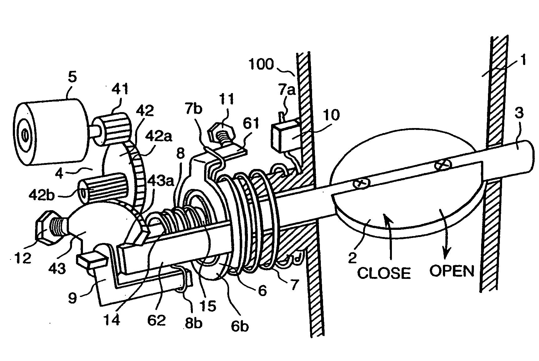
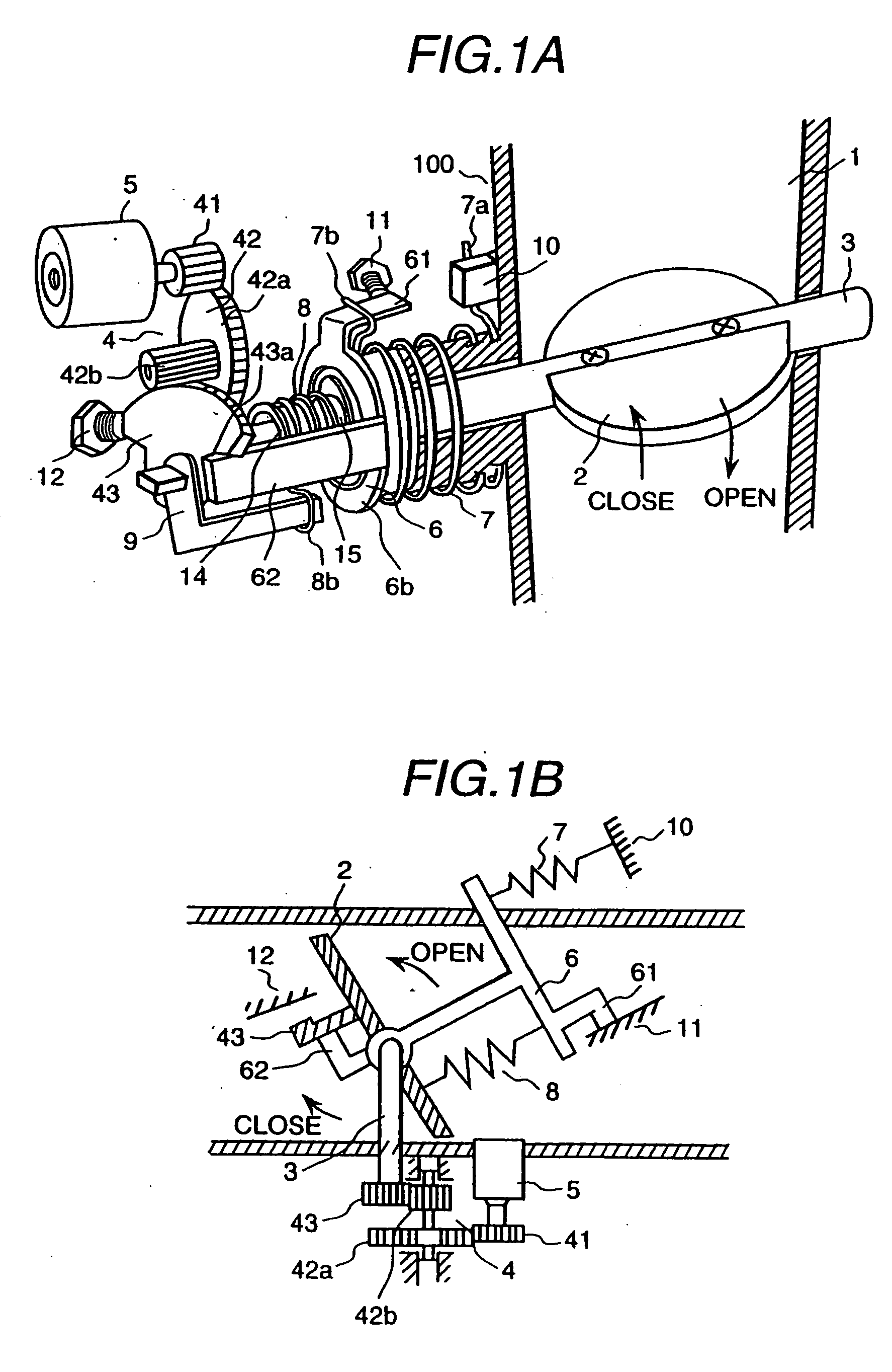
[0054] Initially, the principle of an embodiment of an electronic control throttle device with a default mechanism (a throttle device of an internal combustion engine for a vehicle) in accordance with the present invention will be described below, referring to FIGS. 1A and 1B. FIG. 1A is a schematic perspective view showing an electric drive mechanism of throttle valve and a default mechanism in the present embodiment, and FIG. 1B is an explanatory view equivalently expressing the above-mentioned mechanisms.

[0055] Referring to FIGS. 1A and 1B, a flow rate of air flowing in an intake air passage 1 is adjusted corresponding to an opening degree of a disk-shaped throttle valve 2. The throttle valve 2 is fixed to a throttle valve shaft 3. In one end of the throttle valve shaft 3, a final stage gear (referred to as a throttle gear) 43 of a gear mechanism (a reduction gear mechanis...


PUM


Abstract

A returning spring 7 of the electronic control throttle and a default spring 8 for securing an initial opening degree (default opening degree) of the throttle valve 3 have diameters different from each other, and both of the springs 7, 8 are held around a shaft of the throttle valve shaft 3 and arranged between a gear 43 attached to the throttle valve shaft 3 and a wall portion of the throttle body 100. A shaft supporting gap of the throttle valve shaft 3 is filled with an air leak preventing material, and a minimum opening degree on control purpose of the throttle valve is set to a value larger than an amount of overshoot of the throttle valve occurring when opening degree of the throttle valve is changed from a maximum opening degree on control purpose of the throttle valve to the minimum opening degree.

Description

BACKGROUND OF THE INVENTION [0001] The present invention relates to a throttle apparatus for an internal combustion engine and, more particularly, to an electronic control throttle device which controls opening and closing a throttle valve by driving an electric driven actuator based on a control signal. [0002] In the electronic control throttle apparatus for controlling a throttle valve of an engine by driving an electric driven actuator (for example, a direct current motor, a stepping motor), a technology known is that an initial opening degree (default opening degree) of the throttle valve in an off state of engine key (in other words, at not energized state of the electric driven actuator) is set to a position larger than its full close position. [0003] Here, the full close position does not mean a position for completely choking the intake air passage. Particularly, in a throttle device performing idling rotating speed control using only a throttle valve without any bypass pass...

Claims


Application Information

Patent Timeline
IPC IPC(8): F02D9/02F02D9/10F02D11/10F16N15/00
CPCF02D9/1065F16N15/00F02D2200/0404F02D11/10
Inventor WAYAMA, EISUKEUSUI, TOSHIFUMITOKUMOTO, SHIGERUSAITO, YASUO
Owner HITACHI LTD
Why Eureka
Try Eureka