Self-draining vacuum breaker

a vacuum breaker and self-draining technology, applied in the direction of service pipe systems, valve types, transportation and packaging, etc., can solve the problems of hose rupture, inconvenient use, and springs b>6/b> bouncing away and even getting lost, so as to achieve the effect of further fastening

Inactive Publication Date: 2005-08-18
YANG YUNG FANG
View PDF3 Cites 13 Cited by
  • Summary
  • Abstract
  • Description
  • Claims
  • Application Information

AI Technical Summary

Benefits of technology

[0005] The primary objective of the present invention is to provide a self-draining vacuum breaker, which component parts can be promptly picked up and further fastened and assembled conveniently.

Problems solved by technology

Hence, if the winter comes and the temperature drops to the freezing point, the remaining water will freeze to become ice and its expansion may rupture the hose.
However, in the conventional self-draining vacuum breaker 1, there is only a spring 6 contacting against a claw hook 4 of a movable stopper 5 and there is none of any connection between the movable stopper 5 and the spring 6, such that while assembling the self-draining vacuum breaker 1, the movable stopper 5 and the spring 6 have to be installed separately, thereby being inconvenient for the user.
Furthermore, while disassembling the self-draining vacuum breaker 1, the spring 6 tends to bounce away and even get lost due to none of connection with the movable stopper 5 or other component parts.
In addition, the self-draining vacuum breaker 1 needs complex steps to complete the assembly and it is difficult for the user to conveniently pick up the separate component parts during the assembly.

Method used


Image

  • Self-draining vacuum breaker
  • Self-draining vacuum breaker
  • Self-draining vacuum breaker

Examples


Embodiment Construction

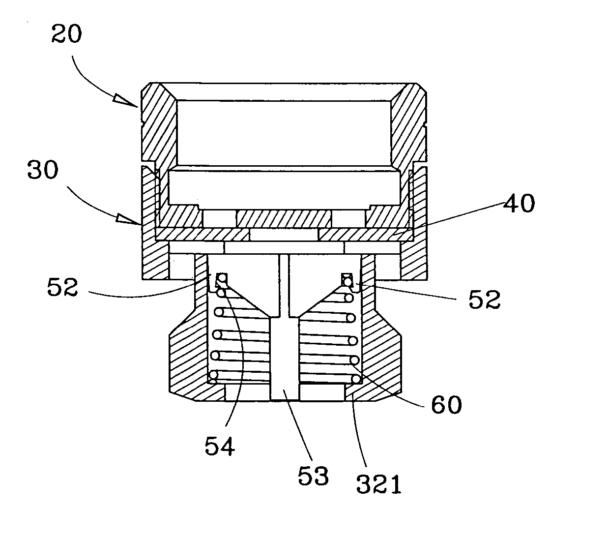
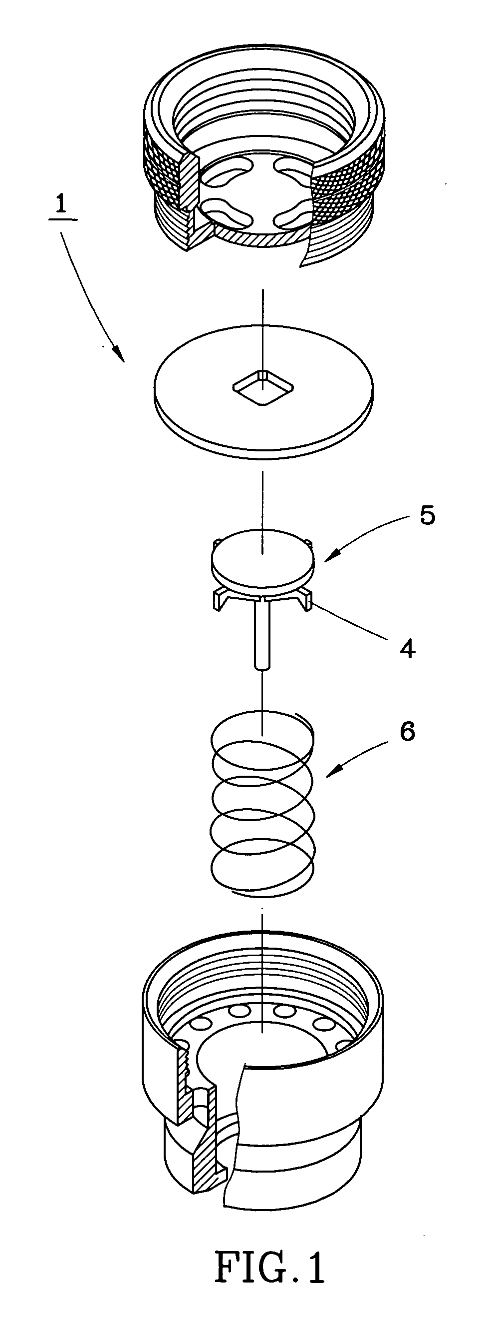
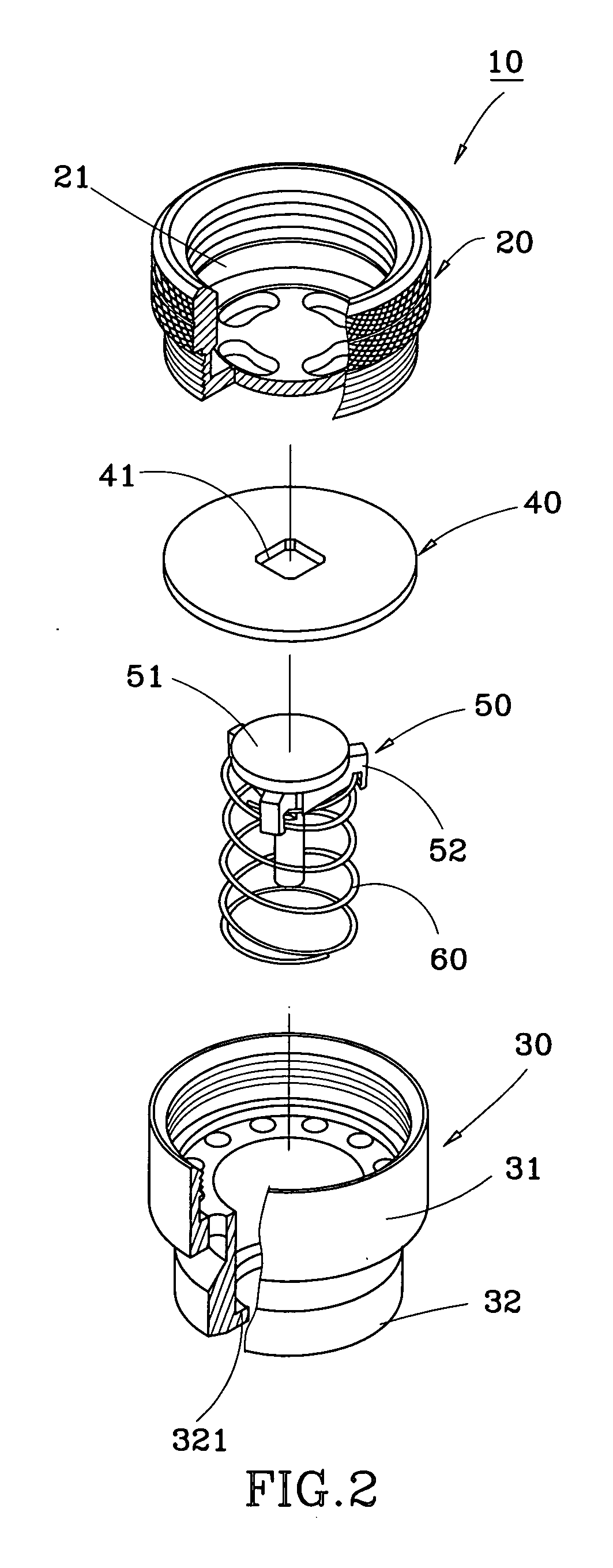
[0013] Referring to FIGS. 2-3, a self-draining vacuum breaker 10 constructed according to a first preferred embodiment of the present invention is comprised of a tubular first valve 20, an internally-stepped tubular second valve 30, a circular diaphragm 40, a movable stopper 50, and a spring 60.

[0014] The first valve 20 includes an inlet 21 formed at an end thereof for connecting an outfall of a faucet (not shown).

[0015] The second valve 30 is threadedly connected with the first valve 20, including a coupling portion 31 formed at an end thereof and having a larger diameter than that of the other end of the first valve 20 and connected with the other end of the first valve 20, and an outlet 32 formed at the other end thereof for connecting a hose (not shown). The outlet 32 has an annular fringe 321 formed radially at a bottom end thereof.

[0016] The circular diaphragm 40 is coaxially mounted in the coupling portion 31 and abutting between the first and second valves 20 and 30, incl...


PUM


Abstract

A self-draining vacuum breaker includes a first valve having an inlet at its one end for connecting an outfall, a second valve having a coupling portion at its one end connected with the other end of the first valve, an outlet at its the other end for connecting a hose, and an annular fringe formed at an inner periphery thereof, a movable stopper having a stopping member and a plurality of claw hooks, which extends downwards from the stopping member and movably contacts against the inner periphery of the outlet of the second valve and each has a barb-like hook portion, and a spring having two ends respectively engaging the barb-like hook portions and lying against the annular fringe.

Description

BACKGROUND OF THE INVENTION [0001] 1. Field of the Invention [0002] The present invention relates generally to automatic drainage system, and more particularly to a self-draining vacuum breaker, which internal component parts are modularized to enhance assembly efficiency and to reduce the trouble of scattering of the component parts during assembly and disassembly. [0003] 2. Description of the Related Art [0004] In a common automatic sprinkler system, when a faucet is switched on, the water flows out of the faucet, through a hose, and then sprays out of a distal end of the hose; when the faucet is switched off, a vacuum is generated in the hose to prevent the water remaining in the hose from drain. Hence, if the winter comes and the temperature drops to the freezing point, the remaining water will freeze to become ice and its expansion may rupture the hose. To solve this problem, a conventional self-draining vacuum breaker 1, as shown in FIG. 1, was developed, certainly eliminating...

Claims


Application Information

Patent Timeline
Patent Type & Authority Applications(United States)
IPC IPC(8): A62C35/68E03B7/10F16K24/02
CPCA62C35/68F16K24/02E03B7/10F16K24/06Y10T137/3331
Inventor YANG, YUNG-FANG
Owner YANG YUNG FANG
Why Eureka
Try Eureka