
Coalescing and separation arrangements systems and methods for liquid mixtures

Inactive Publication Date: 2005-08-18
PALL CORP
View PDF6 Cites 23 Cited by
  • Summary
  • Abstract
  • Description
  • Claims
  • Application Information

AI Technical Summary

Benefits of technology

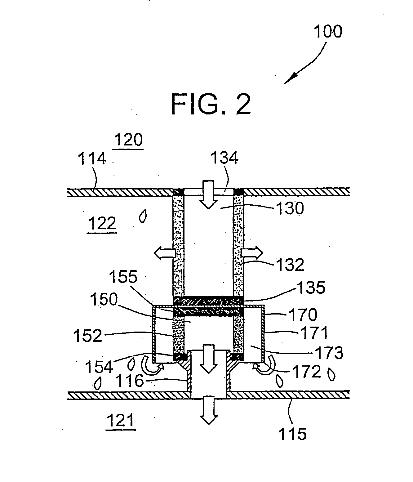
[0020] Embodiments of the present invention may include one or more of these various aspects of the invention. Embodiments which include a flow director and / or which direct the continuous phase liquid in a curvilinear flow path provide many advantages. For example, the discontinuous phase liquid may diverge from the flow path of the continuous phase liquid as the continuous phase liquid flows around a flow director and / or in a curvilinear flow path, for example, to a separator. Consequently, the amount of discontinuous phase liquid which comes in the vicinity of, e.g., contacts, the separator may be significantly reduced. Therefore, the separator may be mostly contacted by the continuous phase liquid and less contacted by the discontinuous phase liquid. Blockage of the separator by the discontinuous phase liquid may be minimized and little, if any, discontinuous phase liquid may be forced through the separator by the continuous phase liquid, greatly enhancing the separation efficiency and allowing smaller separators and, therefore, smaller housings to be used.
[0021] Embodiments which include a conical separator may also provide several advantages, especially for liquids that have a high viscosity or similar specific gravities. A conical separator may have a larger surface area than, e.g., a planar, or flat, separator having a similar dimension. Further, a conical separator may provide a self-cleaning action that sweeps any droplets of the discontinuous phase liquid away from the sloped surface of the separator. Thus, blockage of the separator by the discontinuous phase liquid may be reduced, the separation efficiency may be enhanced and smaller housings may be used.
[0022] Embodiments which include a separator disposed in the interior of a coalescer are also very advantageous. For example, the arrangement of the coalescer and the separator may be much more compact, e.g., shorter. Consequently, the housing may be much more compact.

Problems solved by technology

However, arrangements such as these and other separator and coalescer arrangements, while having many advantages, may produce less than ideal separation results in many applications and may be more expensive to manufacture than is economically feasible.
For example, poor separation may result when the continuous phase liquid has a high viscosity, e.g., is somewhat thick, and / or when the continuous and discontinuous phase liquids have similar specific gravities such that one liquid does not readily float on top of or sink to the bottom of the other liquid.
Regardless of the viscosity or specific gravity of the liquids, poor separation may also result whenever the discontinuous phase liquid is in constant contact with and / or builds up near or on the surface of the separator, especially for high-flow rate or high velocity industrial and laboratory applications.
However, this approach dramatically decreases throughput, i.e., the amount of separation product that can be produced by the system in a given period of time.
These approaches dramatically increase the cost of the system.
Thus, along with issues of poor separation, industry has been confined to approaches that decrease throughput and increase equipment costs.

Method used


Image

  • Coalescing and separation arrangements systems and methods for liquid mixtures
  • Coalescing and separation arrangements systems and methods for liquid mixtures
  • Coalescing and separation arrangements systems and methods for liquid mixtures

Examples


Embodiment Construction

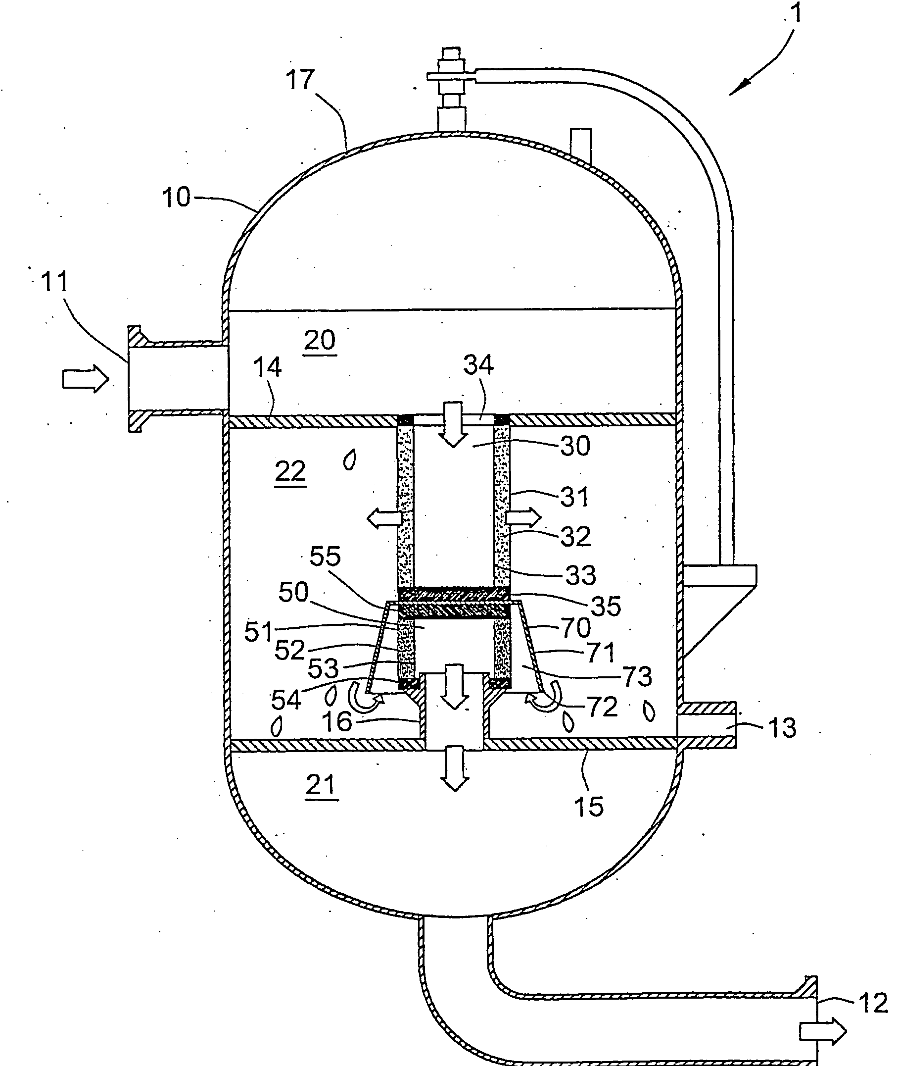
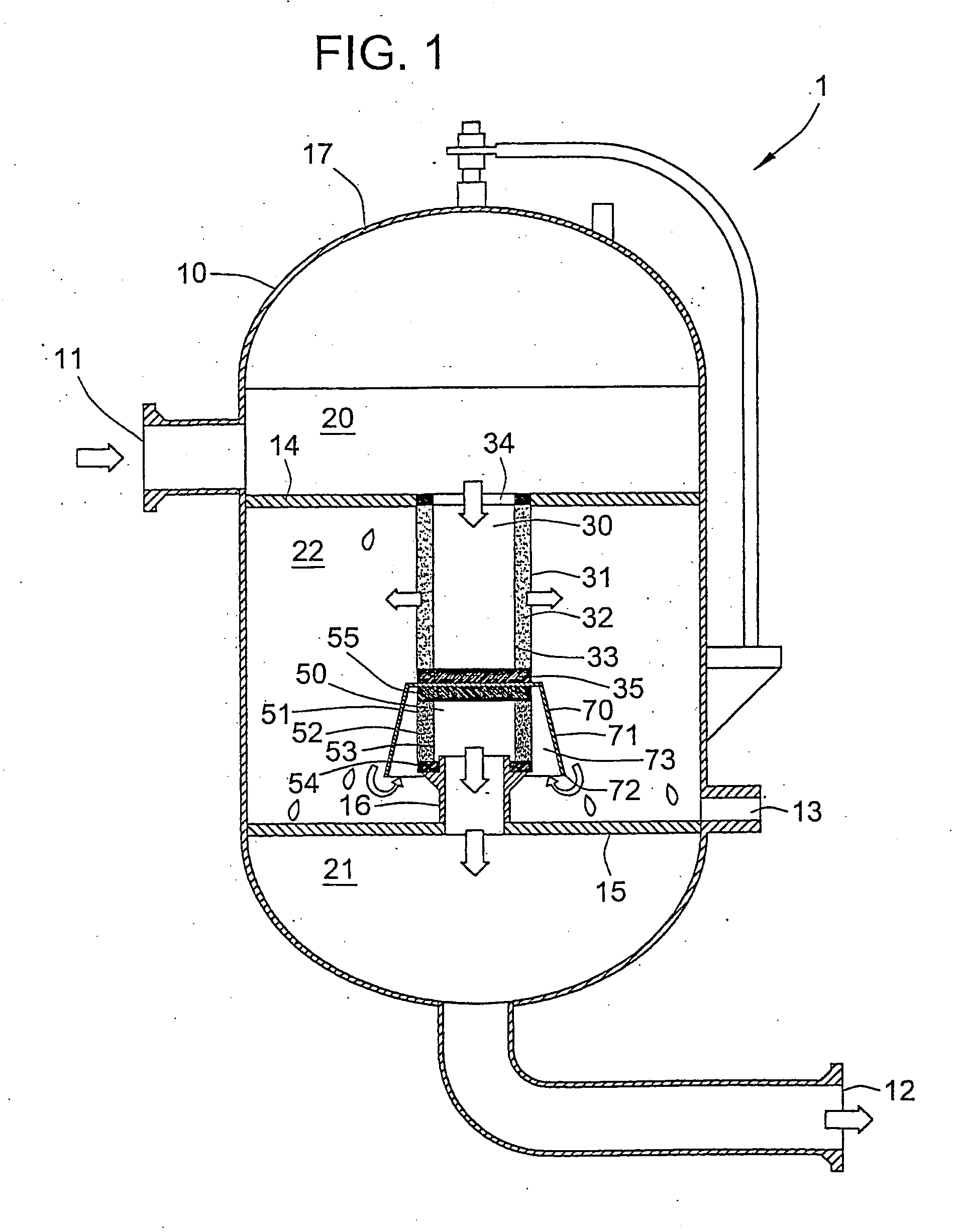
[0036] The present inventions may enhance the separation of immiscible liquid components of a process fluid comprising a mixture of the components. For example, the present inventions may enhance separation of one or more immiscible liquid components of the mixture, as the discontinuous phase, from one or more liquid components of the mixture, as the continuous phase.

[0037] One example of a fluid, or liquid / liquid, treatment system 1 is illustrated in FIG. 1. The fluid treatment system 1 may comprise a housing or a vessel 10, one or more coalescers 30, and one or more separators 50. The housing or vessel 10 may include at least one inlet and at least one outlet. Preferably, the housing 10 may include a process fluid inlet 11 and two or more outlets, e.g., a continuous phase outlet 12 and a discontinuous phase outlet 13, and defines liquid flow paths from the process fluid inlet 11 to the continuous phase outlet 12 and to the discontinuous phase outlet 13. The inlet and the outlets ...


PUM

PropertyMeasurementUnit
Flow rateaaaaaaaaaa
Lengthaaaaaaaaaa

Abstract

Coalescing and / or separating arrangements for separating a discontinuous phase liquid from a continuous phase liquid may comprise two or more of a coalescer (30), a separator (50) and a flow director (70).

Description

TECHNICAL FIELD [0001] The present invention relates to arrangements, systems, and methods for liquid / liquid separations. More particularly, the invention relates to arrangements, systems, and methods for coalescing and separating at least one immiscible liquid component, as the discontinuous phase, from another liquid component, as the continuous phase. BACKGROUND OF THE INVENTION [0002] In many different types of fluid processing, it is often necessary to separate mixed immiscible liquid phases or components from one another. Common devices used to separate mixtures into individual liquid components include coalescers and separators. When two or more immiscible components are very well mixed, coalescers may be used to aid separation by causing small particles of the discontinuous phase liquid to aggregate and form larger droplets within the continuous phase liquid. The discontinuous phase liquid may be heavier or lighter than the continuous phase liquid. Separators may be used to ...

Claims


Application Information

Patent Timeline
IPC IPC(8): B01D17/02B01D29/50B01D29/56B01D29/58B01D29/88
CPCB01D17/0211B01D17/045B01D17/08B01D17/10
Inventor GEIBEL, STEPHENWILLIAMSON, KENNETHWHITNEY, SCOTTGRIFFIN, ANGELAJAMES, ROBERT
Owner PALL CORP
Learn More