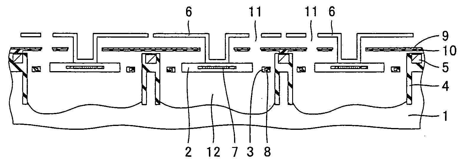
Thermal infrared sensor device and thermal infrared sensor array
- Summary
- Abstract
- Description
- Claims
- Application Information
AI Technical Summary
Benefits of technology
Problems solved by technology
Method used
Image
Examples
first embodiment
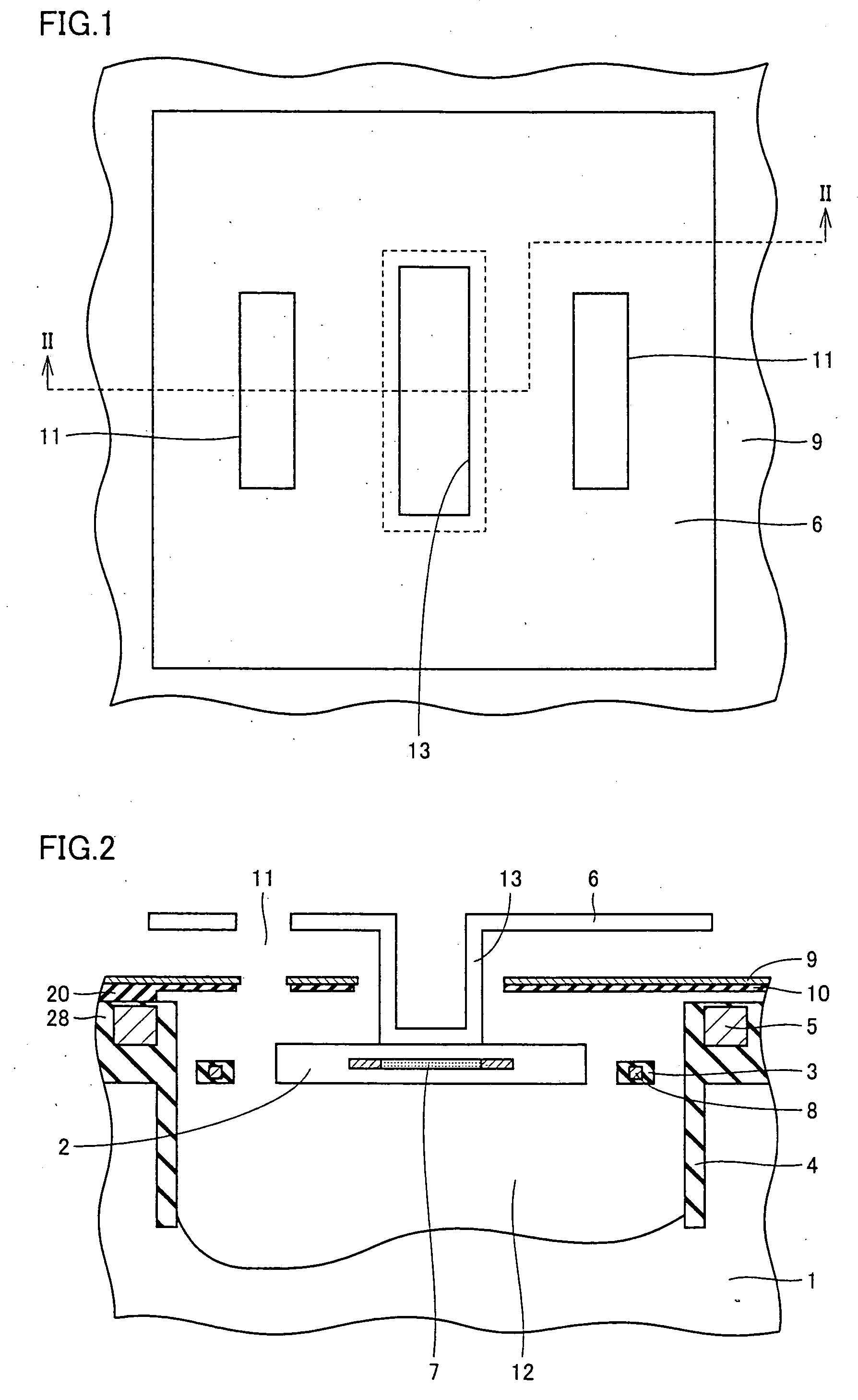
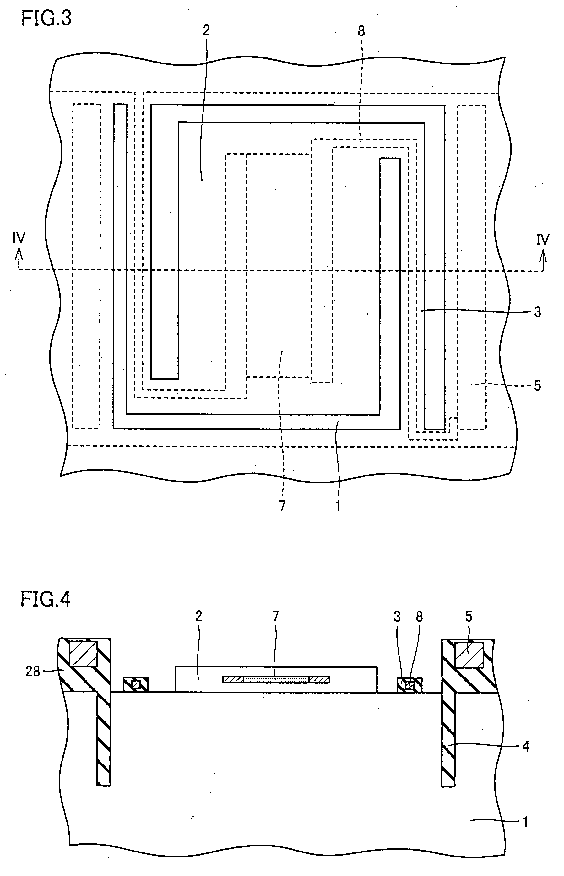
[0025] Referring to FIGS. 1 and 2, a thermal infrared sensor device in a first embodiment in accordance with the present invention will be described. When the thermal infrared sensor device is-seen from above, an absorbing hood portion 6 is provided to cover an infrared reflecting film 9, as shown in FIG. 1. Absorbing hood portion 6 has substantially at its center a depression with a pillar portion 13, and also has two etching holes 11 disposed at positions slightly apart from the depression so as to sandwich the depression. FIG. 2 shows a cross-sectional view taken along line II-II in FIG. 1. Below absorbing hood portion 6, a concave portion 12 is formed in a substrate 1. Substrate 1 is for example a silicon substrate.
[0026] The thermal infrared sensor device includes a temperature detecting portion 2 for converting a change in temperature into an electrical signal. Temperature detecting portion 2 is connected to substrate 1 via a supporting leg 3 to be held at an upper portion of...
second embodiment
[0042] Referring to FIG. 8, a thermal infrared sensor device in a second embodiment in accordance with the present invention will be described. The thermal infrared sensor device has basically the same structure as that in the first embodiment, except that the thermal infrared sensor device in the present embodiment does not have a portion corresponding to anchor portion 20 in the first embodiment (see FIG. 2), and support 10 is directly provided on the upper side of interconnection protecting insulating film 28, as shown in FIG. 8.
[0043] This thermal infrared sensor device can be obtained by partially modifying the method of manufacturing the thermal infrared sensor device described in the first embodiment. More specifically, when forming sacrificial layer 22, it is provided so as to have a height nearly equal to that of interconnection protecting insulating film 28. Thereafter, an opening is formed in a region of sacrificial layer 22 which will later be concave portion 21, and su...
third embodiment
[0046] Referring to FIGS. 9 and 10, a thermal infrared sensor device in a third embodiment in accordance with the present invention will be described. When the thermal infrared sensor device is seen from above, absorbing hood portion 6 is provided to cover infrared reflecting film 9, as shown in FIG. 9. Absorbing hood portion 6 has substantially at its center a depression with pillar portion 13, and also has two etching holes 11 disposed at positions overlapping the depression so as to sandwich the depression. FIG. 10 shows a cross-sectional view taken along line X-X in FIG. 9. Otherwise, the thermal infrared sensor device in the present embodiment has a structure similar to that described in the first embodiment, such as having concave portion 12 formed in substrate 1 below absorbing hood portion 6.
[0047] In the present embodiment, etching hole 11 is formed by providing an opening in a region including a side face of pillar portion 13, as shown in FIG. 10. With this structure, com...
PUM
 Abstract
Description
Claims
Application Information
 - R&D
- Intellectual Property
- Life Sciences
- Materials
- Tech Scout
- Unparalleled Data Quality
- Higher Quality Content
- 60% Fewer Hallucinations
Browse by: Latest US Patents, China's latest patents, Technical Efficacy Thesaurus, Application Domain, Technology Topic, Popular Technical Reports.
© 2025 PatSnap. All rights reserved.Legal|Privacy policy|Modern Slavery Act Transparency Statement|Sitemap|About US| Contact US: help@patsnap.com


