Valve with compact actuating mechanism

a technology of actuating mechanism and valve, which is applied in the field of valves to achieve the effects of high mechanical energy density, high mechanical capacity of work, and high energy efficiency

Inactive Publication Date: 2005-08-18
CHRISTOPH MIETHKE +1
View PDF12 Cites 13 Cited by
  • Summary
  • Abstract
  • Description
  • Claims
  • Application Information

AI Technical Summary

Benefits of technology

[0013] The use of elements in wire form made from a shape memory alloy (SMA) makes it possible to realize an energy-efficient and compact actuating mechanism for the valve member of the valve. Shape memory alloys have the property of returning to their original shape after they have been heated to a temperature above a threshold temperature. The person skilled in the art is aware of numerous metal alloys, such as for example TiNiPd, TiNi, CuAl, CuZnAl or CuAlNi, which have these properties. Shape memory alloys have by far the highest mechanical energy density, i.e. the highest mechanical capacity of work per unit volume. The highest energy efficiency can be achieved in particular with elements in wire form made from a shape memory alloy, also referred to below as SMA wires. When they are heated, for example by a flow of electric current, these SMA wires contract in the longitudinal direction and in the process can perform mechanical work. In the case of the present valve, at least two SMA wires of this type are required, since each SMA wire can only act as an actuator in one direction. The mechanical energy which is provided by each of the two actuators serves primarily to move the valve member, but must also be sufficient to cause the SMA wire which has already been shortened and acts in the opposite direction to stretch back to the original length. On account of the high energy efficiency of shape memory alloys in wire form of this nature, the present valve can be operated with minimal energy consumption. A further advantage is that the present actuating mechanism, in which just two SMA wires are disposed and have to be acted on with a current, for example, in order to be heated or actuated, can be of very compact and space-saving implementation. In particular, this actuating mechanism is able to effect movements of the valve member not only in the μm range but also in the mm and cm range.
[0014] In a particularly advantageous configuration, the present valve is realized as a ball valve with binary opening characteristics. In this case, the valve member, which is formed as a ball, is located in the stable disposition both in the open position and in the closed position with the actuating mechanism unactivated, and consequently no energy need be applied to maintain the open and closed states of the valve. This saves energy, since energy is only required to switch between the open position and the closed position but not to maintain one of the two end positions of the valve. In the closed valve position, the valve member in ball form is located in a sealing manner on the passage opening, and in the open position rests laterally beside the passage opening, in a recess in the base body. The actuating mechanism displaces the valve member between these two positions. It is preferable for the two stable positions of the valve member in ball form to be assisted by an elastic element, for example a coil spring, which presses the valve member onto the passage opening or the recess as appropriate. In one configuration of this ball valve with a binary opening characteristic, a ball with a diameter of approx. 3 mm is used, and the actuating mechanism has to move this ball approx. 1.5 mm between the open and closed positions. This requires an initial force of approx. 30 mN, which can readily be applied by the actuating mechanism described above.

Problems solved by technology

This saves energy, since energy is only required to switch between the open position and the closed position but not to maintain one of the two end positions of the valve.

Method used


Image

  • Valve with compact actuating mechanism
  • Valve with compact actuating mechanism
  • Valve with compact actuating mechanism

Examples


Embodiment Construction

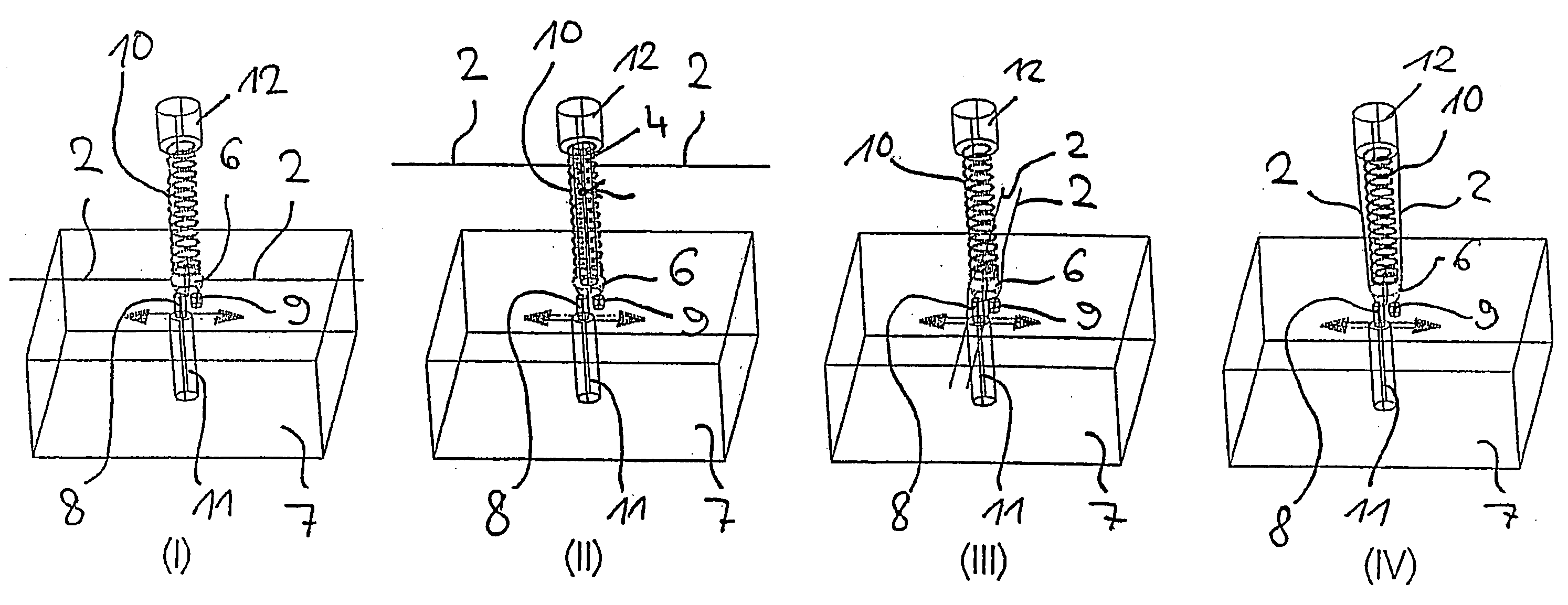
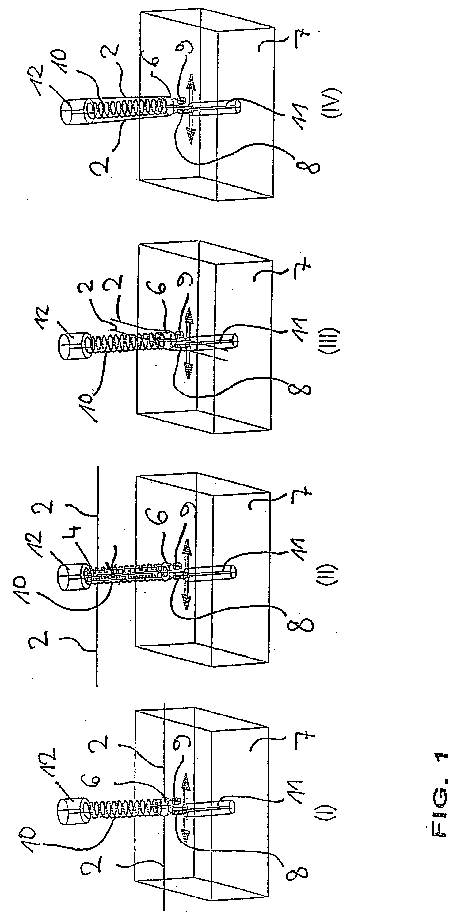
[0020]FIG. 1, in the four sub-figures (I)-(IV), shows four different options for the positioning of the SMA wires 2 of the present actuating mechanism relative to the base body 7, as well as the valve member 3, which may be formed as a ball 6, of the present valve. The four sub-figures in this case serve only to provide illustration in principle, and consequently further elements of the valve, such as for example the way in which the SMA wires are secured, are not illustrated.

[0021] All the sub-figures diagrammatically depict the base body 7 of the valve with the passage opening 8 which is disposed therein and opens out into a valve outlet 11. Next to the passage opening 8, a recess 9 with a blind end is formed in the base body 7, also referred to below as the valve base. In all four illustrations, the ball 6 is above the valve opening 8 in the closed valve state and above the recess 9 in the open valve state. In all cases, the ball 6 is held on the desired position by an elastic m...


PUM


Abstract

The present invention relates to a valve which comprises a base body with a passage opening, a movable valve member for closing and opening the passage opening and an actuating mechanism for moving the valve member in order to open the passage opening. The actuating mechanism comprises at least two elements made from a shape memory alloy which are secured to the base body or a carrier body connected thereto, and can be alternately shortened in the event of the temperature rising above a threshold temperature and are connected to the valve member in such a way that the valve member can be moved from a position on the passage opening into a position alongside the passage opening when one element is shortened on one side and can be moved back into the position on the passage opening when the other element is shortened on one side.

Description

[0001] This application is a continuation of international patent application no. PCT / DE2003 / 002380 filed on Jul. 15, 2003 and claims the benefit of German patent application no. 102 33 601.6 filed on Jul. 24, 2002, both of which applications are incorporated herein and made a part hereof by reference. BACKGROUND OF THE INVENTION [0002] The present invention relates to a valve, in particular a ball valve, which comprises a base body with a passage opening, a movable valve member for closing and opening the passage opening and an actuating mechanism, by means of which the valve member can be moved in order to open up the passage opening, the actuating mechanism having at least two elements in wire form made from a shape memory alloy, which are secured to the base body or a carrier body connected thereto and can be shortened in the event of the temperature rising to a temperature above a threshold temperature. [0003] Valves play an important role in many technical fields in order to c...

Claims


Application Information

Patent Timeline
Patent Type & Authority Applications(United States)
IPC IPC(8): F16K31/70F16K31/00
CPCF16K31/002
Inventor BIEHL, MARGITMIETHKE, CHRISTOPH
Owner CHRISTOPH MIETHKE
Why Eureka
Try Eureka