Plug-in coupling for fluid systems

a fluid system and plug-in technology, applied in the direction of hose connection, pipe/joint/fitting, mechanical apparatus, etc., can solve the problems of accidental detachment of joined parts, inability to consider advantageous, and need for such a special tool, etc., to achieve convenient assembly, simplified detachment, and high stability

Active Publication Date: 2005-08-18
VOSS AUTOMOTIVE
View PDF6 Cites 14 Cited by
  • Summary
  • Abstract
  • Description
  • Claims
  • Application Information

AI Technical Summary

Benefits of technology

[0005] The object of the present invention is to create a plug-in coupling for fluid systems of the aforementioned type, that is to say in particular one with a direct lo

Problems solved by technology

After joining the parts of the quick-fit connector together, it is possible to turn these parts in relation to one another, although for certain applications this cannot be regarded as advantageous.
The need to use such a special t

Method used


Image

  • Plug-in coupling for fluid systems
  • Plug-in coupling for fluid systems
  • Plug-in coupling for fluid systems

Examples


Embodiment Construction

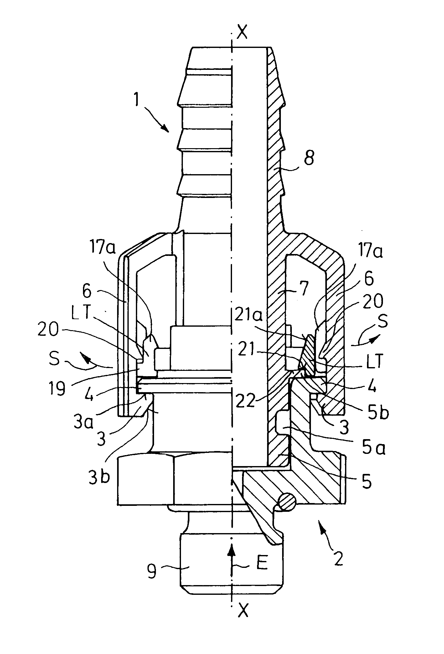
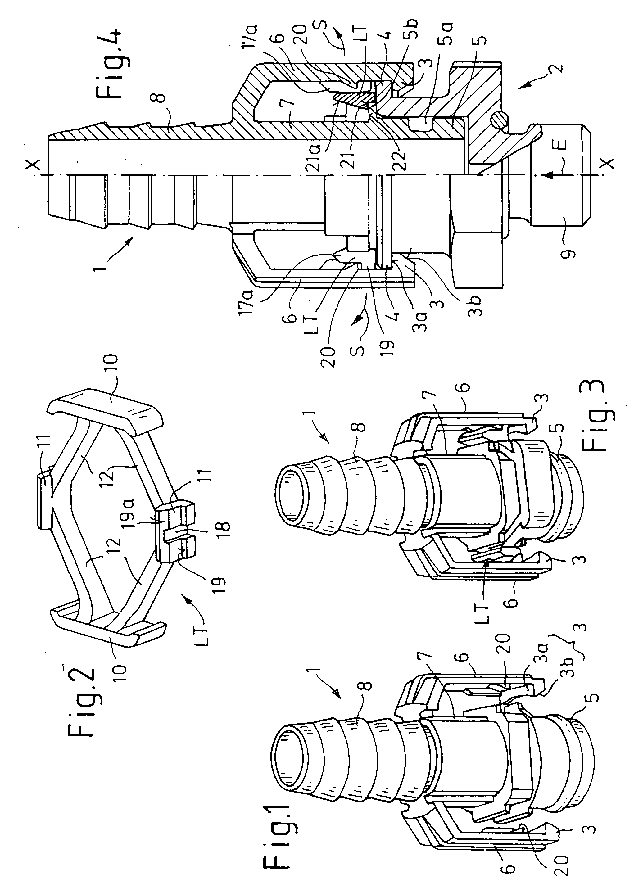
[0034] As will first be seen from FIGS. 1 to 4, a plug-in coupling for fluid systems according to the invention, in particular a quick connect coupling, comprises two tubular interconnectable coupling parts 1, 2, having catches 3, 4 to connect the respective parts 1, 2 together.

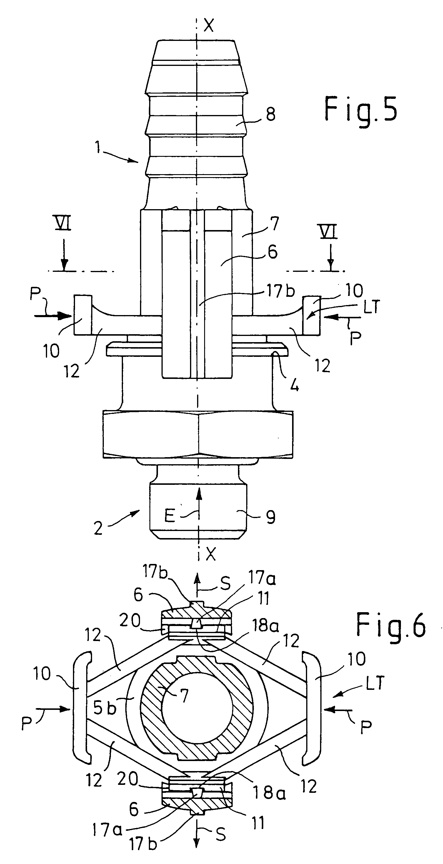
[0035] The first coupling part 1 (shown separately in FIG. 1) has an end union section 5 by means of which it can be plugged into the second coupling part 2 as shown in FIG. 4 (and also in two further main views in FIGS. 5 and 6). The first coupling part 1 also has at least one end retaining section 6 which supports its catches 3 and is formed in all the embodiments described below by two diametrically opposing retaining arms. The catches 3 of the first coupling part 1 grip over an outer peripheral contour of the second coupling part 2 on which catches 4, designed to complement the catches 3 of the first coupling part 1, are formed.

[0036] The catches 3 of the first coupling part 1 are each formed by a catch...


PUM


Abstract

The invention relates to a plug-in coupling for fluid systems having two coupling parts connectable to one another, which each have coordinated catches for connecting them together, one of the coupling parts having an end union section, by means of which it can be plugged into the other coupling part, and one of the coupling parts having at least one end retaining section carrying its catches, by means of which section it grips over an outer peripheral contour of the other coupling part, on which the coordinated complementary catches are formed. In order to achieve a simplified means of detachment whilst ensuring ease of assembly and a highly stable connection of such a plug-in coupling, it is proposed to provide a separate release part, which in the assembled state is held on the first coupling part and/or the second coupling part and which serves for separating the locking connection between the catches of the first coupling part and the catches of the second coupling part.

Description

BACKGROUND OF THE INVENTION [0001] The present invention relates to a plug-in coupling for fluid systems, having two coupling parts connectable to one another, which have coordinated catches for connection with each other. One of the coupling parts has an end union section, by means of which it can be plugged into the other coupling part, and one of the coupling parts has at least one end retaining section carrying its catches, by means of which section it grips over an outer peripheral contour of the other coupling part, on which the coordinated complementary catches are formed. [0002] Such a coupling is described in DE 38 43 995 C1, which desired a quick-fit connector for the connection or attachment of a hose or pipe. The known connecting arrangement has a housing part (first coupling part) and a core part (second coupling part), which can each be firmly connected at one end to a hose, pipe or appliance. A seal is arranged between the core part and the housing part. In the housin...

Claims


Application Information

Patent Timeline
IPC IPC(8): F16L37/00F16L37/08F16L37/084
CPCF16L37/0982F16L37/0841F16L37/084
Inventor BRANDT, JOSEFKAMINSKI, VOLKERBILSTEIN, ROZALIA
Owner VOSS AUTOMOTIVE
Why Eureka
Try Eureka