Prestressing structure for rotationally balancing a motor

Inactive Publication Date: 2005-08-18
SUNONWEALTH ELECTRIC MACHINE IND
View PDF8 Cites 16 Cited by
  • Summary
  • Abstract
  • Description
  • Claims
  • Application Information

AI Technical Summary

Benefits of technology

[0014] The primary objective of this invention is to provide a prestressing structure for rotationally balancing a motor, which includes a motor rotor and a motor sta

Problems solved by technology

The mass of the magnetically conductive metal plate 301 may also result in a heavy burden of the motor rotor 30 that may result in reduction of motor speed.
Consequently, it may result in abrasion of the bearing member 21 in long-term use.
However, the magnetically conductive metal plate may result in reduction of excitation efficiency of pole plates of the motor stator which is in connection with the magnetically conductive metal plate.
Moreover, the magnetically conductive metal plate may result in a short circuit of a printed circuit board which is in connection with the magnetically conductive metal plate.
However, the upright wall of the magnetically conductive metal plate may occupy a partial space for distributing blades of the motor rotor when the

Method used


Image

  • Prestressing structure for rotationally balancing a motor
  • Prestressing structure for rotationally balancing a motor
  • Prestressing structure for rotationally balancing a motor

Examples


Embodiment Construction

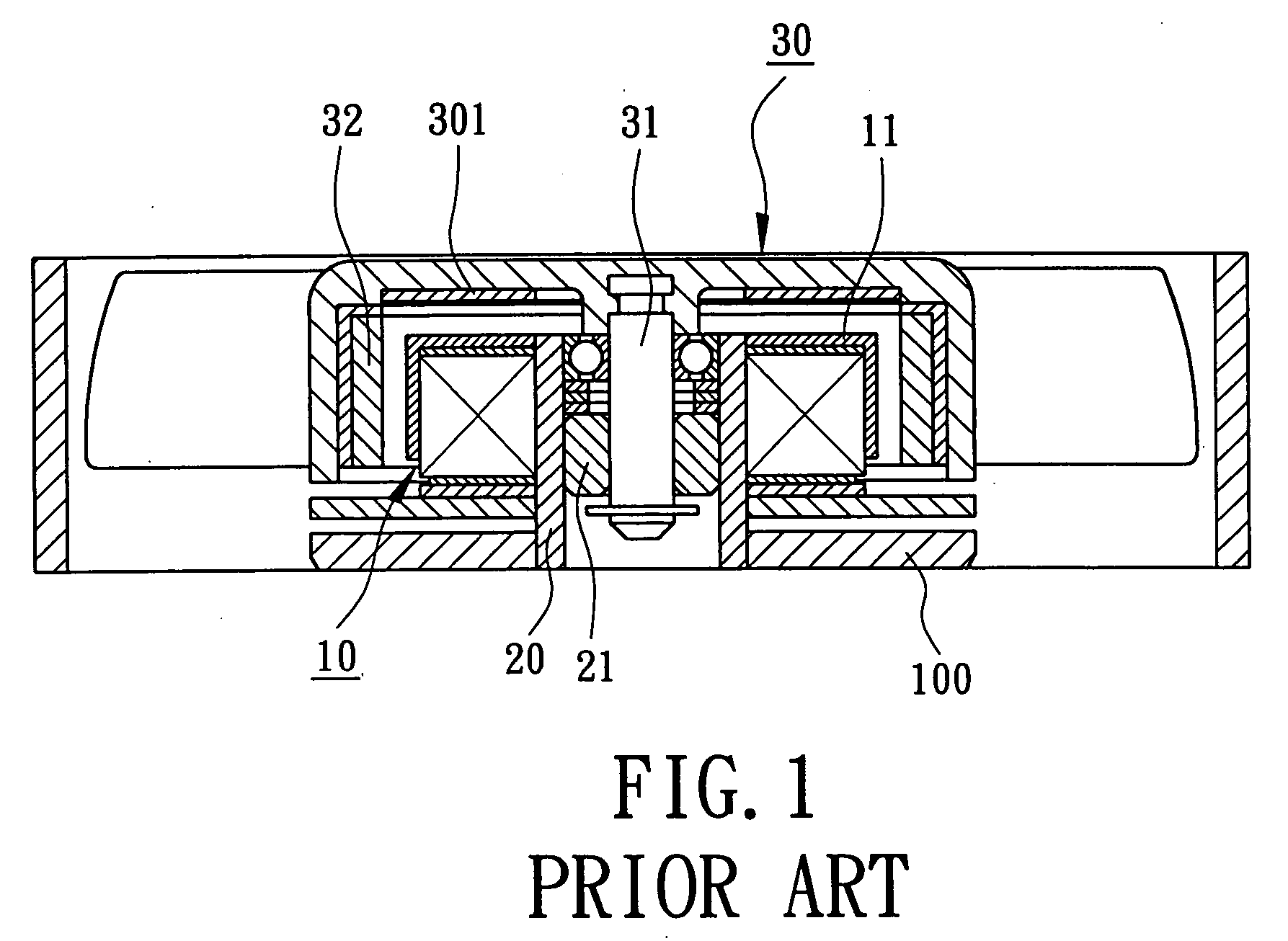
[0028] Referring to FIGS. 2 through 9, reference numerals of the first through sixth embodiments of the present invention have applied the identical numerals of the conventional motor members, as shown in FIG. 1. The construction of motor members in accordance with embodiments of the present invention have similar configuration and same function as that of the conventional motor members and detailed descriptions may be omitted.

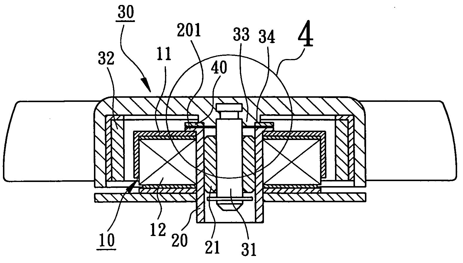
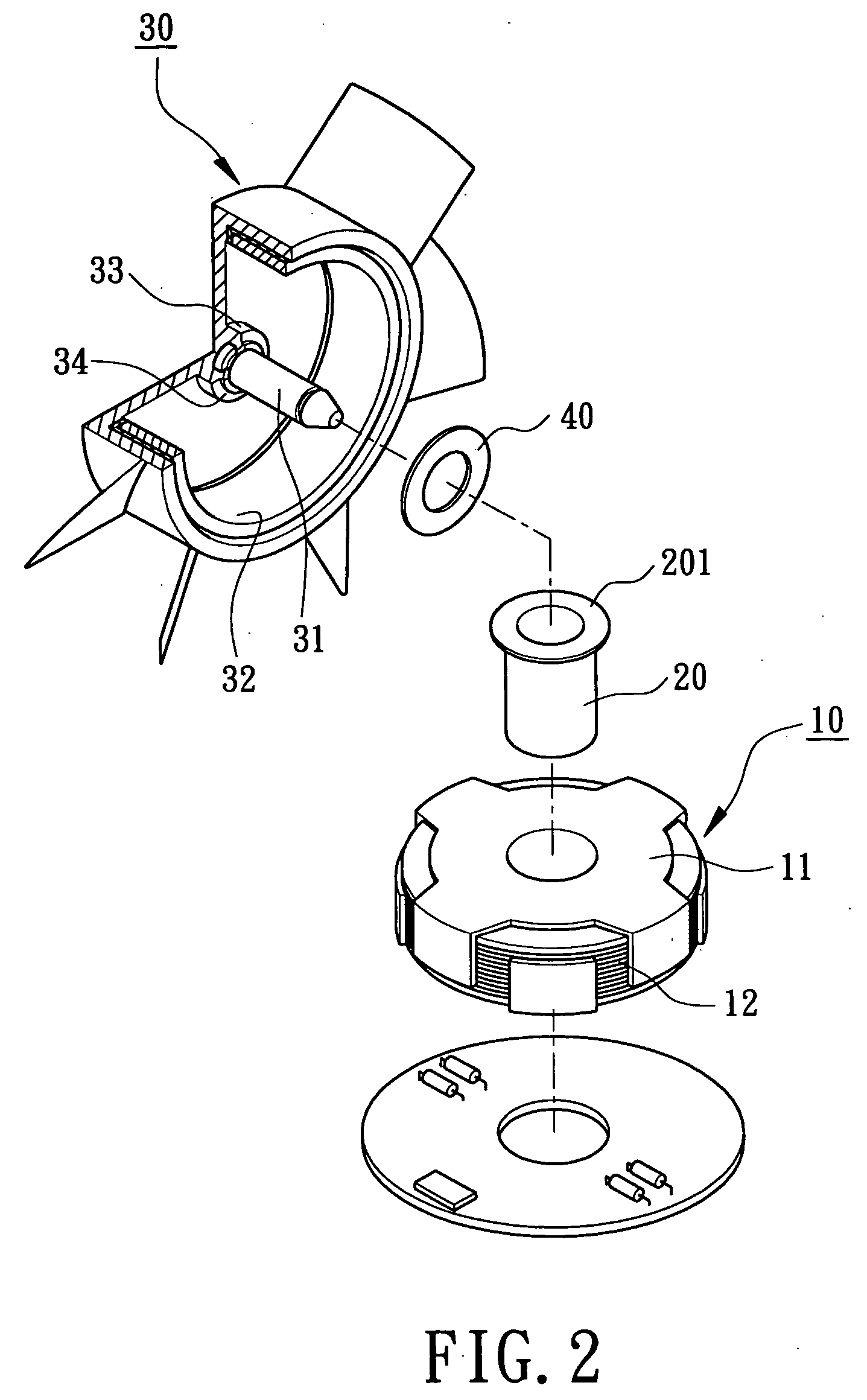
[0029] Referring to FIGS. 2 through 4, a prestressing structure for rotationally balancing a motor in accordance with a first embodiment of the present invention includes a motor stator 10, a magnetically conductive member 201, a motor rotor 30 and a balancing magnet 40.

[0030] Referring again to FIGS. 2 through 4, construction of the motor stator 10 shall be described in detail. The motor stator 10 consists of at least one pole plate 11 and at least one coil 12. The pole plate 11 of the motor stator 10 may be alternatively magnetized when a current and a cou...


PUM


Abstract

A prestressing structure for rotationally balancing a motor includes a motor stator, a motor rotor, a magnetically conductive member and a balancing magnet. The motor stator has an axial hole and an axial tube extending therethrough. An end of the axial tube provides with the magnetically conductive member. The motor rotor has an inner surface and a shaft seat mounted thereon. A top portion of the shaft seat provides with the balancing magnet which has at least one surface successively attracting at least one surface of the magnetically conductive member for stabilizing rotary movement of the motor.

Description

BACKGROUND OF THE INVENTION [0001] 1. Field of the Invention [0002] The present invention relates to a prestressing structure for rotationally balancing a motor. More particularly, the present invention relates to a motor rotor and a motor stator employing a balancing magnet and a magnetically conductive member to generate a prestressing force therebetween so that rotary balance of the motor is maintained. [0003] 2. Description of the Related Art [0004] Referring initially to FIG. 1, Taiwanese Patent Publication No. 383818, entitled “HEAT DISSIPATION FAN STRUCTURE HAVING A MAGNETICALLY POSITIONING DEVICE,” discloses a conventional rotational balance structure for a motor. The motor includes a motor stator 10, an axial tube 20, a motor rotor 30 and a magnetically conductive metal plate 301. The motor stator 10 employs the axial tube 20 to mount on a hub base 100, and provides with a plurality of pole plates 11. The axial tube 20 accommodates a bearing member 21 that allows a rotary m...

Claims


Application Information

Patent Timeline
IPC IPC(8): H02K1/04H02K5/24H02K7/08H02K7/09
CPCH02K7/085F16C25/045H02K7/09F16C2360/46
Inventor HORNG, ALEXHONG, YIN-RONG
Owner SUNONWEALTH ELECTRIC MACHINE IND
Why Eureka
Try Eureka